For the free-electron maser design we describe in Prototype free-electron maser design, it is essential to model the magnetic fields in the undulator as well as in the collimating magnets and magnetic lenses. This nearly conducting computational magnetostatics, since the magnetic fields do not have an exact analytical solution for all but the simplest cases. We will give a brief guide for how these simulations are performed.
Introduction to magnetostatics
We will start by giving a basic overview of magnetostatics. Magnetostatics describes the behavior of charges in time-independent magnetic fields. This is only an approximate description of electromagnetism, but works well when the fields vary very gradually (or not at all) in time. The two fundamental equations of magnetostatics are two of the Maxwell equations (Gauss’s law and Ampere’s law) in the time-independent regime, and take the form:
Where is the total current density, is the magnetic field, is the demagnetizing field, and the latter two are related by the constitutive relation of magnetostatics:
Where is the magnetization of the material. Solving these equations for different boundary conditions allows us to find the fields, and therefore the trajectory of particles within these fields. The study of boundary-value problems (BVPs) in magnetostatics, and in particular the specific BVPs that we encounter in modelling free-electron lasers/masers, are discussed within this guide.
General formulation
To start, we are concerned with finding the magnetic field outside an arbitrary permanent magnet (we will discuss specific geometries later). It is also possible to find the fields in the interior of the magnet, but this is less useful for our particular applications, so we first consider the external fields only.
Outside a permanent magnet, assuming there are no significant currents present and magnet is surrounded by a non-permeable medium (), then simplifies to . Then it is possible to write in terms of a potential , where is the magnetic scalar potential, and satisfies . By substituting into Gauss’s law () where in the surrounding region, we arrive at:
Therefore, after straightforward simplifications, we arrive at Laplace’s equation for the magnetic scalar potential:
This can be solved in the exterior case to arrive at the following analytical solution1:
For a uniform permanent magnet, the magnitude of the magnetic field when no external field is applied (that is, ) is defined to be equal to its magnetic remanence ; thus from the constitutive relation for magnetic fields, we have2:
Therefore, using this definition, the integral can be evaluated explicitly, though an analytical expression can only be found for simple geometries; the integral must be evaluated numerically (for instance, via Monte-Carlo methods or numerical quadrature) for all other cases. Here, we will take the example of a rectangular bar magnet, for which the surface integral can be done analytically. This corresponds with the magnetic geometry and type used in our undulator design, which uses permanent magnets only (as shown below).

Thus, in our case, where , and the integral becomes:
Once the magnetic scalar potential is computed, the magnetic field can then be found from:
Analytical solutions
In general, the integral solution for the magnetic scalar potential can only be solved exactly in the case of very simple and highly-symmetrical geometries, such as the four geometries shown below:
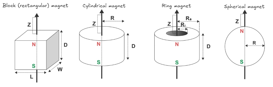
Diagrams originally from supermagnete.de
The below analytical formulas correspond to the above magnets, where is the magnetic remanence as before3, and the axis points from the south pole of the magnet to its north pole:
There is, however, no general solution and the integral must generally be done numerically or approximated.
Derivation of exact solution for block magnet
Note: The below section uses the coordinate conventions and symbol notation given at the start of this guide. They are different from the conventions used in the analytical formulas for permanent magnets.
Let us assume that the magnets are of rectangular geometry, and have length , width , and depth , where the length is measured along the axis, the width is measured along the axis, and the depth is measured along the axis. Thus, the rectangular cuboid we are integrating over is defined by . To make this integral more tractable, we can assume that the magnets are “thin” magnets and thus set , giving us the slightly “simpler” integral:
Where here we need only integrate over one surface (by symmetry, whether we choose this to be the front or back of the magnet doesn’t matter) as opposed to the six integrals that would otherwise need to be done for . Thus the surface integral reduces to the following double integral:
To solve this integral, we first integrate with respect to with the following substitution:
Now we may use the following identity:
Which allows us to evaluate the integral in as follows:
Now, substituting in the explicit form of , we have:
With the substitution we obtain the two integrals in a slightly simpler form:
Both of the resulting integrals in the sum are integrals of the form:
This is an integral that can be evaluated using integration by parts or (more conveniently) by consulting a computer algebra system; the solution is given (up to a constant) by[^7]:
Where we will not write out explicitly in the rest of the solution for simplicity. Thus we have:
Where we define as:
And thus the complete solution can then be written succinctly as:
While appearing deceptively-simple, this succinct answer expands out to 12 terms(!) in total, making it highly impractical to use for actually compute this solution. A much more numerically-usable solution can be found by not evaluating the integral in , giving us:
Where the function (here ) is defined by the following integral:
And thus the magnetic field can be found (via ) to be:
The numerical derivatives here can be found by finite differences, but the analytical derivative can also be found by differentiating under the integral sign; that is:
Note that for small , while for very large . If we consider the magnetic field far away from the magnet, then becomes very small; hence we can apply the small approximation, giving us:
Substituting this result into our analytical expression for gives us:
However, since we assume is large, thus and . Thus the above result becomes:
Hence, we see that the magnetic scalar potential (and thus magnetic field) of a permanent magnet drops off extremely rapidly to zero at large distances. This is why a fridge magnet is not dangerous, even though the magnetic remanence of its material may be quite high. A different scenario emerges, however, when we consider the magnetic field close to the surface of the magnet, that is, for small . In this case, we use the large approximation of , giving us:
This integral is straightforward to evaluate, and gives:
Therefore, the magnetic scalar potential is given by:
From which we may find to be:
It is useful to note that this contains a term that can be expanded as a geometric series:
Hence, assuming that then one has:
Hence the magnetic field generally satisfies an inverse-square law at short distances and can be incredibly strong near the surface of a permanent magnet.
Solving with a CAS
In theory, the surface integral can also be evaluated with the following Mathematica code:
yprime = Subscript[p, y]
zprime = Subscript[p, z]
Integrate[
	 1/Sqrt[x^2 + (y - yprime)^2 + (z - zprime)^2],
	 {yprime, 0, L}, {zprime, 0, w}
 ]
Or with the following SymPy code:
from sympy import *
x, y, z = symbols("x y z", real=True)
Br, w, L = symbols("B_r w L", constant=True,
		real=True, positive=True)
mu0 = Symbol(r"\mu_0")
yprime, zprime = symbols("y' z'")
prefactor = Br/(2*pi*mu0)
integrand = 1/sqrt(x**2 + (y-yprime)**2 + (z - zprime)**2)
integral = Integral(integrand, (yprime, 0, L), (zprime, 0, w))
psi = prefactor * integral.doit()
Eq(Symbol(r"\psi_m"), psi)
However, both SymPy and Mathematica time out when trying to compute the integral; it is likely that neither can compute it, even if they are given longer times, due to the complexity of the integral.
Far field of a permanent magnet
The dipole model is a very basic approximate model for the magnetic field of a permanent magnets. It models permanent magnets as magnetic dipoles, regardless of their geometry. This assumption is made by assuming that the separation between the magnets at the top and bottom of the undulator is large compared to the cross-sectional width of the magnets, so the magnets can be thought of as point-like.
Let us select a coordinate system where be the direction the magnets are pointing and be the direction of the particle beam. The undulator is composed of pairs of north-north and south-south facing magnets, arrayed along the axis: let us choose just a single pair to begin our analysis. Each pair is separated by distance , where we let the electron beam be along and the two magnets be placed at and respectively.
The far-field behavior of a dipole magnet is very different. Indeed, we find that the magnetic field roughly follows an inverse-cube law:
We can derive this in a straightforward way. To start, the magnetic field of a single magnet with constant magnetization could be approximated as a perfect dipole at distances “far” from the magnet, which has a magnetic field given by:
The magnetic moments of the pair of magnets are identical (both facing along either or , and of the same magnitude). We will consider a pair facing along to begin our analysis. Previously, we have already found that:
Where is the magnetic remanence (an intrinsic material property) of the magnet, and is the magnet’s volume.
Note: We adjusted the previously-derived formula since the magnetic fields and therefore magnetic moments of the magnets are aligned along .
We now apply more simplifying assumptions: namely, that since the magnets are “far” from each other and from the electron beam, then the term drops off rapidly and can be effectively ignored. In addition, since the magnetic moment of the magnets are on the axis between the magnets (that is, along , the direction), the magnetic field would be primarily concentrated along as well, so we can effectively ignore . This leaves us with:
Using this approximation, the magnetic fields of the upper magnet and lower magnets in the pair are therefore, respectively:
And by the superposition principle, their combined field is given by:
At , which is the position of the electron beam, we therefore have:
We can now use the approximation that is very large compared to , so we have:
And at , that is, right between the two magnets, where the electron beam is located, we find that:
While this expression becomes infinite (and thus unphysical) at , showcasing the limitations of our model, we note that rapidly decays by the inverse cube of the distance, so even at a small (but nonzero) distance we have . Therefore, we may approximate the ambient field as:
Now using , we obtain the ambient field strength between the magnets:
This yields field strengths of about 1/1000th of a Tesla - not ideal at all, at least for magnets of a small volume. However, recognize that this is only the case for large , meaning that the paired magnets are far apart from each other. If the two magnets are brought close to each other, the dipole approximation breaks down; however, if we make the approximation of small , or at least where at least one dimension of the magnet’s geometry is roughly equal to , then we have , giving us
From which we may obtain fairly high field strengths of . Note that if one of the dimensions is greater than times the separation distance , then we have and we can achieve very high field strengths of up to or even more.
Basic experiment using a simple compass magnet
A rudimentary way to test the correctness of this theoretical result is with a simple toy experiment. Place a small compass needle near a pair of alternating neodynium magnets. Here is the magnetic moment of the test (compass-style) magnet, which has a magnetic remanence approximately that of Earth’s magnetic field (, where ). Thus its magnetic moment magnitude is:
Where is the compass needle volume. Meanwhile, is the ambient field generated by the primary magnet. We assume that the test magnet does not disturb the field to a great degree. The magnetic field of each magnet would have the following magnitude, as per our calculations:
We would expect the magnetic field to vary sinusoidally along the alternating magnets, but as a first approximation, we can assume the magnetic field to vary linearly along the axis between them. Thus, the field in between the two magnets is then:
The magnitude of the force on the compass needle due to the ambient field is given by:
Assuming small oscillations, we can model this as simple harmonic oscillator, where , where is the length of the test magnet needle and is its mass. Therefore, we have:
Note: It should be pretty evident that this can yield at most an order-of-magnitude agreement with theory. An EMF meter and a much more sensitive experiment would be necessary for anything more precise.
Interior-exterior case
We will now consider the more complicated case where we solve for both the interior and exterior magnetic fields. This involves a more complicated boundary-value problem that generally cannot be solved analytically, even in integral form. Instead, numerical methods are necessary for most cases.
To formulate the problem, we must consider the pertinent boundary conditions. First, we impose the boundary condition that the magnetic scalar potential vanish at infinity, that is:
In practice, this boundary condition is only useful analytically; simulating an infinitely-large domain numerically is impractical (though there are some numerical methods that can do so, such as the boundary element method), so we can simply set a cutoff radius (which is large compared to the size of the magnet), giving us:
Next, we consider the boundary conditions at the interface between the interior of the magnet (with permeability ) and the exterior of the magnet (with permeability ). When the relative permeability (which is approximately true for many ferromagnetic materials), then just outside the surface of the magnet4, (the tangential component) becomes zero and (the normal component) becomes the only component of ; this is exactly analogous to the perfect conductor in electrostatics. Therefore, at the surface of the magnet, we obtain the following Neumann boundary condition:
Where denotes the surface of the magnet, denotes the coordinate tangent to the surface, and where the solution is valid for the entirety of the exterior of the magnet. Meanwhile, we may determine using the standard boundary conditions for magnetostatics, given by:
Where is the effective surface current density, is the field just underneath the surface of the magnet, and is the field just outside the magnet (assumed to be vacuum or another non-permeable medium). Then by substitution, one has:
More precisely, the above is only true if are nearly normal to the surface (which occurs in the limit of very high relative permeabilities). In the general case, we have:
Where are the normal components of the fields, respectively. Now, to determine , we use the constitutive relation . Here it is implied that represent the interior fields and magnetizations; that is, , , . We must now impose a constitutive relation between and to solve. In general, this relationship is nonlinear for permanent magnets, and thus . However, for many permanent magnets5 we can make the linear approximation given by6:
Here, is the recoil permeability of the material and is a material constant, where we can often make the assumption (which is true for a perfect magnet). From these boundary conditions, we can then solve for the fields both inside and outside the magnet.
Magnetic field of an undulator
An undulator, as described in Free-electron maser physics, is a device that uses an oscillating magnetic field to stimulate the emission of synchrotron radiation. In an undulator, dipole magnets are arranged such that the magnetic field lines (shown as arrows in the below image) alternate up and down, which lead charge particles to follow sinusoidal trajectories as they pass between the magnets.
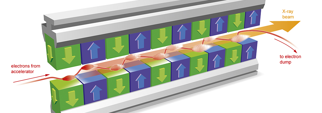
Source: European XFEL
The simplest model of the magnetic field of an undulator has been discussed already at length; it is given by:
However, this is an approximation and only applies in the on-axis region. In the more general case, the magnetic field of an undulator can be derived from the magnetic scalar potential obtained by solving the (exterior) magnetostatic equation , and the solution is given by4:
Where is the magnetic scalar potential. Upon differentiation, the magnetic field is thus:
If we take a cross-section of the field in the plane at some fixed location at along the optical axis, we have:
Alternatively, letting be a constant, this can be also written as:
A plot looks something like this (where the vertical direction points from the north pole of one magnet to the south pole of another):
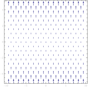
is the horizontal coordinate, is the vertical coordinate, in accordance with standard conventions for free-electron laser physics.
Note that this is with an idealized case in which we assume that the magnetic field in the direction is zero; this assumption is only valid for small . For real magnets, and grows larger the further away you are from the magnet. Thus, we can make the ansatz , at least for .
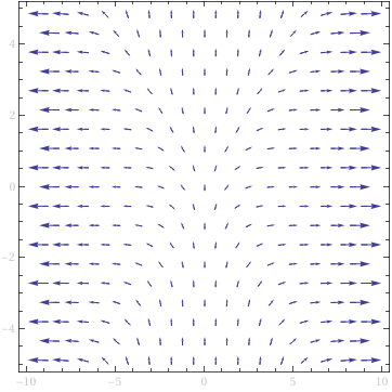
For we can make the ansatz , giving us:
A cross-section plot of the field for constant but varying and is shown below:

With such a complicated field, finding electron trajectories analytically would be extremely difficult. But it is important to note that this is still not the exact field because it does not model the dipole magnets themselves; it treats them as magnetic point dipoles. While this is acceptable as a mean-field approximation, it is inaccurate at distances very close to the magnets, where the geometry of the magnets does matter. Methods to model realistic undulators can be found in Numerical simulations for magnetostatics.
Magnetic field of a magnetic lens
Magnets are also essential for magnetic focusing: controlling and collimating charged particle beams. The type of magnets used depends on the application: both permanent magnets and electromagnets can be used. Regardless of the type, magnetic lenses are typically one of two categories:
- Multipole magnetic lenses, which compress, stretch, and/or squeeze particle beams using a combination of multipole magnets
- Thin solenoid lenses, which use a thin solenoid (basic electromagnet) instead of multipole magnets
Let us first consider the case of multipole magnets. Multipoles are a class of magnets built out of two, four, six, or even eight magnets, arranged in a symmetrical fashion. These are correspondingly referred to as dipoles, quadrupoles, sextupoles, and octupoles, reflecting the number of magnets typically used in each configuration, as shown below:

Diagram of multipole magnets. Note: orange arrows represent magnetic field lines.
A multipole magnet’s field can be assumed to be constant (or zero) along , that is, . However, are in general non-constant, meaning that and . It is conventional to use complex numbers to represent the magnetic fields of multipole magnets, since they are naturally suited for describing two-dimensional vector-like quantities. Note that the use of complex numbers is purely for mathematical convenience; magnetic fields are of course real-valued. But by making use of this formalism, the magnetic field of a multipole magnet can be written very simply as a power series of an analytic function in the complex plane1:
Where are constant coefficients that can be real or imaginary. From the above, it follows that:
A dipole magnet (that is, a single magnet with two poles) is represented by the first term () of the series. To describe a quadrupole (four magnets with four poles), we include the second () term. To describe a sextupole magnet, we also include the third () term, hence the name “sextupole” (which comes after the dipole (first) term and the quadrupole (second) term). It is noteworthy that the dipole term corresponds to a constant magnetic field; the quadrupole term corresponds to a magnetic field that varies linearly with distance; and the sextupole term represents a magnetic field that varies quadratically with distance. (Continuing on this progression, the octupole term represents a field that is cubic with respect to the distance.)
Note: For the purposes of our discussion, the precise values of don’t matter, since we’re only interested in the qualitative characteristics of the solution, which are not affected by the values of the constants.
In general, dipole magnets are used for beam steering (that is, turning a beam left or right), sextupoles are used for correcting the effects of chromatic aberration6 (a form of misalignment caused by energy differences in the beam), and octupoles are used for beam stabilization5. However, of the different multipoles, only quadrupole magnets can be used for beam collimation: that is, focusing charged particles and keeping them closely-clustered. This cannot be done with a single quadrupole magnet alone; rather, a pair of quadrupole magnets (also called a quadrupole doublet) is required for this purpose2. The two quadrupoles respectively squeeze the charged particles horizontally- and vertically-together, allowing for a formation of a collimated beam, as is evident from the following graphs (from the Feynman lectures):

Original source: Feynman lectures II, Ch. 29.7
A thin solenoid lens, by contrast, is effectively a tightly-wound coil of wire, made such that it has an extremely short length. This has a similar effect as a single loop of wire in that it causes electrons to spiral inwards in helical paths as they pass through the coil. This method is used by deflection yokes on cathode-ray tubes (CRTs) in old television sets, and is notably much simpler; it is not very difficult to simply coil a wire and run a current through it. In addition, while solenoids are generally weaker than natural magnets at low current, it is possible to use a ferromagnetic (e.g. iron) core to greatly increase the magnetic flux density. A basic comparison between the two types is given below; for a more comprehensive treatment, refer to (Hofmann, 2013).
| Type of magnetic lens | Advantages | Disadvantages |
|---|---|---|
| Quadrupole doublet | Can use permanent magnets (no external power source), widely-used in research | Complex design, not as easy to make, difficult to control |
| Thin solenoid lens | Simple design, widely-used in commercial equipment, easy to control by adjusting current | Requires constant power to provide current for electromagnet |
Numerical simulations
We should mention that in our prior discussion, we generally considered only cases where an analytical solution can be found for the , , and fields. However, this is not possible in most cases, and we can only use numerical simulations. More details on this topic can be found in Numerical simulations for magnetostatics.
Footnotes
-
See the presentation Magnetic Multipoles, Magnet Design by Krafft et. al. at Jefferson Lab ↩ ↩2
-
A sextupole magnet notably cannot be used for beam collimation; it can only twist a beam into a triangular shape. See here for more details. ↩ ↩2
-
Originally from this site (archived version) ↩
-
P. Schmüser et al., Free-Electron Lasers in the Ultraviolet and X-Ray Regime (2nd ed.), Ch. 2 pg. 11 ↩ ↩2
-
If we use two sextupole magnets of opposite polarities (that is, one flipped so all N-S pairs become S-N pairs), the two lenses can act as a combined converging-diverging lens. This means that rather than diverging the beam (as with a single sextupole magnet), the two magnets correct beam aberrations and restore the beam back to a circular shape, hence improving the quality of the beam. ↩ ↩2