An essential metric of any power system is the efficiency at which the system operates. That is to say, how much of the power generated ends up being useful power, after mechanical, transmission, and technical losses are taken into account? This is a question of the utmost importance, and it is essential to give figures backed by calculations to be able to determine the total efficiency of a system rigorously.
Components of power loss
In a space-based power system, there are many possible sources of power losses:
- Solar collector losses
- Power satellite losses, which occur in the conversion from visible light into other wavelengths
- Transmission losses due to atmospheric attenuation
- Receiver losses for the power stations on the ground
Solar collector and power satellite losses
The first source of losses comes from the solar collector (that is, the solar mirror). Since we plan to use a very large solar mirror made of composite, very thin segments, the main source of loss (other than surface imperfections and imperfect attachment of the segment during construction) comes from the mirror coating. Assuming silver as our coating for both primary and secondary mirrors, which has an average reflectance of between 95-97% over the majority of the solar spectrum1. Given that this is near-perfect reflectivity, it can be more or less ignored for now, although issues like tarnishing due to micrometeorite impacts and surface imperfections of the very large composite mirror, as well as the (small) obstruction of the primary mirrors by support structs, will need to be examined in the future.
The next source of losses comes from the masers used to convert solar energy into microwaves for transmission to Earth. We have already calculated this efficiency in Free-electron maser efficiency calculations, where we established a figure of 35% max efficiency demonstrated in an experimental setting, and speculated that this could be increased to 50% with advances in technology. Assuming that the waveguides and the parabolic reflectors used for transmission to Earth function as planned to maintain a Gaussian beam profile from the maser, we could add in losses of a few percent to bring down the actual efficiency to 30% (with present technology) or 45% (with future technology).
Atmospheric losses at different wavelengths
Any space-based power system must face the difficulty of sending power through Earth’s atmosphere. This is a major technological obstacle as the atmosphere blocks significant regions of the electromagnetic spectrum. Thus, it is important to identify the ideal wavelengths for power transmission, and determine how these wavelengths affect power loss.
Infrared range
In the infrared range, there are three important parts of the spectrum: the near-infrared range, which encompasses wavelengths between and , the mid-infrared range, which is everything from to , and the far-infrared range, which encompasses wavelengths between to .
We will first examine the near-infrared range. The below graph indicates the atmospheric attenuation by wavelength in this range:2

From Optical Fiber Communications, 6th ed. (2013), chapter 4.3. Note that somewhat confusingly, higher dB values here indicate more transmittance and lower loss.
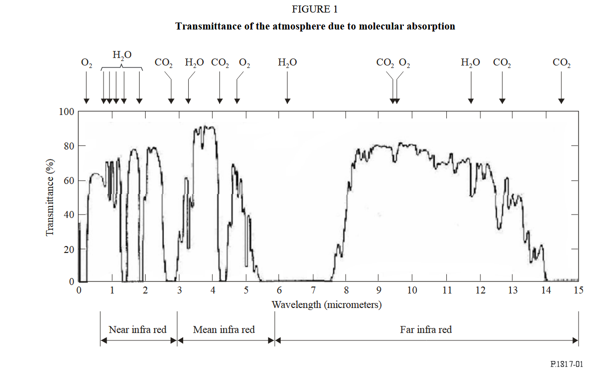
There are several notable infrared windows (regions where infrared radiation passes relatively unimpeded through the atmosphere): the first is around , the second is around , and the third is around . Meanwhile, if we consider the mid-infrared range, we have several additional windows, including the famous infrared window between 3 and the small window around . (The below graph is from A revised concept for improving transmission efficiency).
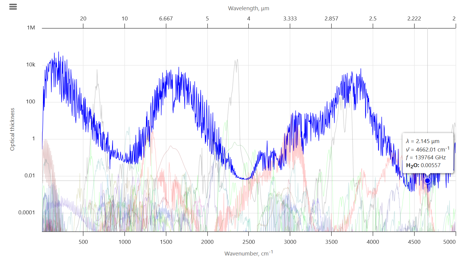
Unfortunately, most other areas of the infrared spectrum, and especially far-infrared, have very high atmospheric attenuation and are out of consideration. Thus, the near-infrared and mid-infrared ranges are the most optimal in the infrared range. These results are also validated by the ITU’s recommendation P.1817-1 on infrared wireless power transmission, as shown in the below plot:
From ITU-R recommendation P.1817-1 (report), page 5.
Once again, we see a peak at around as well as , with transmittance at around 70% and 80% respectively, as well as the well-known infrared window between , with transmittance reaching 80% or higher, at least in clear skies.
However, we have not taken into account different atmospheric conditions that can greatly increase atmospheric attenuation. First, it is important to note that all weather occurs in the troposphere, which extends 10 kilometers from the Earth’s surface (that is, above sea level). Thus, the predominant contributor to atmospheric attenuation from weather is only in the last 10 km of the laser beam path. One significant factor to consider is rainfall. For instance, consider the following graph of attenuation due to rain from the same ITU-R P.1817-1 report:
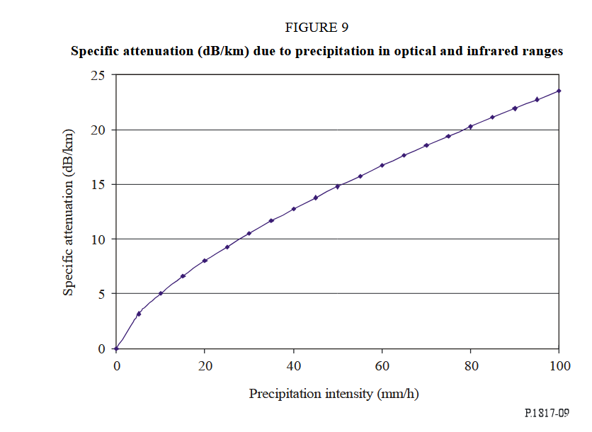
From ITU-R recommendation P.1817-1 (report), page 13.
If we compare these values of rain-based attenuation with the following table of rain intensities4, we find that even a small amount of precipitation can greatly increase transmission losses. The total attenuation is effectively 10x the specific attenuation (to account for the 10 km thickness of the troposphere), meaning that in heavy rain, power can be attenuated from 50 dB to over 150 dB, meaning that effectively 100% of the power of the laser beam is lost. This is a serious disadvantage common to nearly the entire infrared range, but it has a solution, which we will discuss later.
| Rain intensity | Amount of precipitation (rainfall) |
|---|---|
| Light rain | < 2.5 mm/hr |
| Moderate rain | 2.6 to 7.6 mm/hr |
| Heavy rain | 7.7 to 49 mm/hr |
| Violent rain | > 50 mm/hr |
Microwave range
In the microwave range, power transmission losses are much lower as atmospheric losses drop quite drastically. In fact, microwaves pass almost unimpeded through the atmosphere in clear conditions (as shown in the graph below).
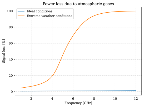
Source code of graph in our Jupyter notebooks
While the higher-frequency portions of the microwave range are blocked rather substantially in poor weather conditions (admittedly something that also happens with infrared radiation), lower frequencies are affected comparatively little; in particular, microwaves are attenuated by less than 10% even in extremely-poor weather conditions.5 However, microwaves suffer from another major issue that leads to substantially higher transmission losses, which we’ll discuss next.
Beam focusing losses
Another important part of the transmission losses concerns the issue of beam focusing. This arises from a fundamental limit in physics - the diffraction limit. By nature of being electromagnetic waves, it is impossible to focus a laser beam to smaller than a certain size, which is given by the Gaussian beam formula:
Where is the spot size (beam radius on the surface of the Earth), is the radius of the laser aperture, is the refractive index, is the transmission wavelength, and is the distance of the power satellite from the Earth. More details can be found in Ideal laser beam divergence and A revised concept for improving transmission efficiency, where we derived that in the case of large distances, the spot size can be well-approximated with:
The diffraction limit means that the minimum spot size is roughly proportional to the square of the wavelength, so the longer the wavelength, the more the laser beam diverges. Assuming a 1 meter radius laser aperture (we explain how to make an aperture of this size in Laser aperture engineering), we find that the spot size increases dramatically with longer wavelengths:
| Wavelength | Minimum spot size |
|---|---|
| 700 nm | |
| 900 nm | |
| 1.1 μm | |
| 1.5 μm | |
| 2 μm | |
| 4 μm | |
| 10 μm | |
| 0.1 mm | |
| 1 mm | |
| 1 cm (30 GHz) | |
| 10 cm (3 GHz) | |
| 20 cm (1.5 GHz) |
Note: For long transmission distances, the spot size is approximately inversely proportional to , meaning that doubling the aperture size halves the spot size, and tripling the aperture size reduces the spot size three times.
This is the issue we discussed with regards to using microwaves: since a microwave beam diverges so quickly, a naive maser design would be impractical since less than a hundred-thousandth of its power would reach a ground-based receiver.
Receiver losses
Another major source of losses is in the ground-based receivers that convert the laser beam back into electricity. This loss can be broken down into several parts.
The first contribution to the receiver loss is in the limited surface area of the receivers. In theoretical calculations, it is useful to imagine a single huge receiver that receives all the power from space. But realistically, rather than constructing one huge receiver, it would be much more feasible to instead construct several smaller receivers arranged in an array. This, of course, would reduce the efficiency of the system. If our beam spot size (the radius of the beam by the time it reaches Earth’s surface) is , and we use circular receivers of radius - ignoring overlaps and ignoring which packing algorithm is used to actually fit said number of circles - the percent loss in surface area between one receiver of radius and the combined area of smaller receivers is given by:
By a geometric theorem by Lagrange, we know that the optimal packing is to use a hexagonal packing system, which can pack a larger circle with smaller circles, losing only about 10% of the surface area in the process when (though if this condition does not hold, there are dedicated tables of optimal circular packing solutions).
Combined losses
Combining all the factors for losses (mirror reflectivity/imperfections, laser inefficiencies, waveguides/reflectors, and beam divergence), we can expect a very optimistic efficiency of a 2GHz system to be about assuming the present state-of-the-art technologies, and around for future technology, assuming a very large ground receiver size of in radius to capture 99% of the beam area. This, of course, is not accounting for the fact that building several-kilometer-sized structures in space has never been done before, so all the components can only be prototyped and ground-tested presently. This makes space-based solar power moderately efficient, but only with extremely large receivers - otherwise, even getting a few kilowatts would be a challenge. The main advantage, of course, is that we can transmit power constantly, day or night, in clear skies or heavy storms, and extremely large solar mirrors counteract the inefficiencies in the process by raw power collected (up to many terawatts!).
| Loss in (modified) dB units | Transmittance in percent |
|---|---|
| 0 | 100% |
| -1 | 79% |
| -2 | 63.5% |
| -3 | 50% |
| -4 | 39.8% |
| -5 | 31.6% |
Footnotes
-
Values come from the optics company ThorLabs, which provides reflectance values for their silver mirrors ↩
-
Note that these loss values are in modified decibel units (dB) and in particular appear to be sign-reversed. Thus when converted into linear percentage units, they take the following values: ↩
-
This is a wavelength in which carbon dioxide lasers ( lasers) may actually be a feasible option, as their principal wavelengths can reach . Unfortunately, their efficiency is quite low at only 20% (though this is high for a laser). ↩
-
Rainfall category intensities are based on this wikipedia article ↩
-
A useful resource to consult for atmospheric attenuation in different weather conditions for different microwave bands is on this radar education website ↩