A critical part of the our space-based solar power system design is, of course, the solar mirrors. Their shape, materials, and engineering is essential in determining how well they can capture solar energy from space. The engineering challenges involved in creating space-based solar mirrors efficiently are tremendous, and we will describe them - and how we solve these challenges - on this page.
Note: See Prototype solar mirror design for more details on a very small-scale implementation of the design. This page will generally focus on the full-scale version, designed to operate in space and generate useful electricity.
Basic design of solar mirrors
On a basic level, the solar mirrors of the power system are parabolic reflectors, meaning that their shape is radially symmetric and can be mathematically described by a parabola - that is, a curve in the form . (To be precise, the shape of a parabolic reflector is technically a paraboloid, which is the 3D surface of revolution obtained by rotating a parabola around the radial axis, but we will dispense with the specific terminology here).
The primary function of a parabolic reflector is to focus parallel rays of light to a single point. More generally, they can work for any type of electromagnetic radiation, including (and very commonly) microwaves and radio waves. The point at which the reflected rays of light converge is known as the focal length of the parabolic reflector, and is denoted as . A parabolic reflector with diameter (where is the radius) and depth has a focal length given by1:
An illustration of the geometric features of the idealized parabolic reflector is shown in the diagram below:

Geometry of a basic parabolic dish. See interactive version on Desmos
Of course, real parabolic dishes are nowhere near this simple, given that we must also account for factors like deviations from the idealized parabolic shape, material imperfections, non-uniform reflectivity, among many others. However, a basic parabola is sufficient as a theoretical description of a solar mirror - at least, for our purposes - and we will see how we can arrive at more accurate results later.
Orbital placement of solar mirrors
For optimal solar collection, we want to make sure that the solar mirrors are always oriented towards the Sun at all points on their orbit. However, this poses a major problem, because at geostationary orbit, the orientation of the Sun with respect to an Earth-facing satellite varies over the course of the day. This means that if the satellite were aligned with a single spot on Earth, it would soon be facing away from the Sun, limiting power collection potential. Solutions to this problem are thus of great interest in our design.
A naive solution
A basic solution to the issue is to split the mirror and the transmitter (the part that creates the power beam) into two separate spacecraft. In this design, the transmitter can move with respect to the mirror so that it is always aligned with the Earth, while the mirror always faces parallel to the Sun:

The advantage of the approach is that it allows the transmitter to always face the Earth, removing the need for ground tracking. However, this approach is wasteful because of the opening in the mirror, which restricts the field of view of the transmitter and reduces available mirror surface area. All said, this design has substantial limitations, so we have come up with an alternate solution, which we will now discuss.
A more sophisticated solution
In the alternate design, we do not use a separate transmitter satellite; instead, the whole power satellite (mirror, maser, and transmission system) is structurally one interconnected system. In this design, the satellite is always oriented towards the Sun, and a system of gimbal mounts is used to align the power beam towards the Earth.
To make the design work, we need two mirrors: a primary mirror and a secondary mirror, a common configuration in large reflecting telescopes on Earth. Meanwhile, two gimbal mounts are used for directing the power beam, one behind and one in front of the satellite. The forward mount is used during the period of the orbit when the satellite is behind the Earth, and the rear mount is used during the period of the orbit when the mirror is in front of the Earth. We illustrate this configuration in the diagram below:

This approach is highly technologically-complex, as it requires an additional secondary mirror, two gimbal mounts (alongside other microwave beamguides), and a way to continuously turn the satellite. However, it allows the primary mirror to be always facing the Sun and thus oriented parallel to the Sun’s rays, ensuring optimal solar power collection.
Mirror design details
As we discussed, while there are a variety of parabolic reflector designs in use, the one we choose is a composite design that has a large primary mirror with a smaller secondary mirror (these can also be referred to as the reflector and subreflector). A particularly popular design of this variety is known as the Cassegrain reflector, and an elaborate Cassegrain design (commonly used for large telecommunications antennas) is shown in the diagram below:

Source: Wikipedia
In our variant of the Cassegrain design, the secondary mirror will be much smaller than the primary mirror, for reasons that will be evident soon. Both mirrors will be segmented and very thin (likely on the order of millimeters). The segments are designed to be launched separately, and lock together in space to form the large primary mirror. In addition, the materials used for the mirror will need to be nearly 100% reflective, while staying light and flexible. This allows them to be folded during launch and expand accordion-style afterwards, saving space and allowing the segments to be launched en masse without requiring massive rockets.
Meanwhile, the struts connecting the secondary mirror to the primary mirror should be made of microwave-transparent materials and can be just thin, flexible cords, since objects in space don’t have to support their own weight. This means they can be curled up during launch and extend once the satellite is in position, again saving space. A simplified diagram of our design is shown below:

A simplified diagram of our concept design.
We can see now that by making the secondary mirror small, the “blind spot” of the forwards power beam can be reduced, ensuring that the beam can be aimed in a nearly 360-degree range - essentially, in any direction other than directly forwards. This ensures that even once the Sun-facing satellite is no longer aligned with the Earth, the power beam can continuously deliver energy to Earth and stay precisely-aimed.
To turn the maser beam will require a beamguide: a system of mirrors and other optical components to precisely direct the maser beam while avoiding power loss. First, a beam splitter will be used to route the beam either to the forward or rear gimbal mount; as we discussed; this can simply be an adjustable-size aperture, which becomes 100% reflective when fully closed (routing the beam entirely forwards) and 100% transmissive when fully open (routing the beam entirely to the rear). Second, mirror(s) will be used to direct the beam towards either one of the gimbal mounts, which each contain a rotating internal mirror to steer the beam. The design of the beamguide system is shown below:

A simplified diagram of the beamguide system.
The beamguide contains no waveguides, as waveguides generally do not support TEM modes (of which the Gaussian beam is one). Using a waveguide would thus disturb the Gaussian profile of the beam and lead to greater beam divergence (recall that the Gaussian beam is the minimum-divergence laser beam possible, so we want to preserve the beam profile as much as possible). Instead, the microwave beams pass entirely through vacuum, which also serves to minimize reflection and absorption. The beam splitters and mirrors are mounted on non-metal trusses and are exposed to open vacuum as well, which also saves weight.
In addition, while the above diagrams show only one pair of beams is shown for simplicity, in reality, the power satellites would have multiple pairs of beams. This allows them to beam power to numerous locations across the world, as shown in the diagram below:

Construction and station-keeping
To be able to build out the massive solar mirrors needed for the system, a large degree of autonomous construction will be needed. The mirror segments will need to autonomously deploy, unfold, and attach together. Rocket launches and assembly must be carefully timed to avoid asymmetric forces on the mirror. The maser beams must be controlled by an on-board computer and rotate at a very precise rate to ensure the beam tracks the ground.
Even after construction is complete, there will continue to be challenges. Micrometeorite impacts, solar wind, and cosmic rays could damage electronics and the solar mirror, requiring redundant computer systems and protective coatings (such as aerogels) that can shield the mirror without adding too much weight or blocking sunlight. In addition, while deep space may appear to be empty, that is not to say that there are no (non-gravitational) forces on the spacecraft. A major concern is radiation pressure, since on a large enough scale our mirrors are essentially solar sails. While radiation pressure is an extremely small effect, it adds up over time, and it becomes substantial for very large mirrors (especially those up to and beyond 100m in radius).
To quantify how substantial radiation pressure can be, we can perform a simple mathematical analysis. We can estimate the change in velocity over a time interval (e.g. a year) by combining the expression for the force due to radiation pressure, given by (where is the average solar irradiance and is the mirror surface area), and the impulse-momentum theorem , giving us:
Assuming that the mirrors are very thin and made of a homogeneous reflective material of mass density (as measured in mass per unit surface area), while the main assembly of the satellite (i.e. everything on the power satellites other than the mirror) has a mass of , this expression reduces to:
Assuming that is small, (where is the total radius of the mirrors), and thus increases quickly as we use larger and larger mirrors. If we take (assuming that the main assembly is reasonably light), for 5-meter mirrors, rises sharply to for 50-meter mirrors, and grows from there. By increasing (e.g. via ballast, which can also act as radiation shielding), we can decrease , but this is expensive and inefficient.
In addition, we have the difficulty of making sure the spacecraft is aligned with the Sun in the first place - which would require that the spacecraft rotate continuously throughout its orbit to face the Sun. This becomes major problem for the large power satellites, which can weigh hundreds or even thousands of tons once fully complete2 and are too heavy to turn with conventional techniques.
Both can be solved by using rocket launches (during orbital assembly) as a form of station-keeping: due to conservation of linear and angular momentum, the momentum of the rocket will be transferred to the power satellite, boosting it against the direction of the Sun and giving it spin. Since space is empty, there will be nothing to slow the power satellite down once it starts spinning, and radiation pressure can be precisely balanced by the transferred (linear) momentum.
This method of boosting is best done during construction, since our mirrors are made of a lot of small segments that autonomously join together, so each piece can transfer a little bit of angular and linear momentum (from the rocket used to launch it) instead of needing to give a large boost of angular and linear momentum all at once (such high impulse could cause major structural damage to the satellite). By continuously adding more and more segments, we therefore gain multiple advantages:
- The power satellites can produce useful electricity from early on, since the segmented, flexible mirror design means that the initial power satellite can be launched with relatively few rockets (instead of the decades required to build a large single-piece mirror and launch it into space)
- The frequent arrival of new mirror segments with rockets can provide continuous boosts to counterbalance against radiation pressure
- The satellites can slowly grow from MW capacity to GW capacity power generation, as the mirror’s surface area grows larger and larger with more segments, meaning more solar energy can be collected
Other design considerations
While precisely-timed rocket boosts can provide sufficient angular and linear momentum to counteract the effects of radiation pressure and keep the spacecraft oriented towards the Sun, this method is impractical for the much smaller prototypes. While the initial launch, if oriented at the correct angle, can provide enough spin and impulse, over time this will no longer be sufficient, meaning that reaction wheels or thrusters (or both, for redundancy) will be needed.
However, this is not as straightforward as it may first seem; spacecraft thrusters predominantly use highly-toxic hydrazine, and reaction wheel failures are a common cause of spacecraft malfunctions. One promising technology that may solve many issues with reaction wheels is to use magnetically-suspended reaction wheels, which, to quote the linked NASA paper, offers “low drag torque, wear-free, unlubricated, vacuum-compatible operation, and unlimited life”.
Additionally, to protect the sensitive electronics in the gimbal mounts (and other parts of the beamguide) from being damaged by cosmic rays and micrometeorite impacts, it may be a good idea to use a radome. Radomes are transparent to long-wavelength electromagnetic radiation (presumably including microwaves) but can provide much-needed shielding for the maser and beamguide; otherwise, micrometeorites, which can have the kinetic energy of a bullet (if not more) at orbital velocities, can seriously damage the electronics.
Solar mirror modelling
Since solar energy is just light, it is modelled by Maxwell’s equations, which govern all forms of light (and other electromagnetic waves). We may find the electric field and radiation pattern of light incident on the mirror by solving the Helmholtz equation, the fundamental partial differential equation that governs the propagation of electromagnetic waves. The Helmholtz equation is given by:
Where is the electric field of the electromagnetic wave and is the wavevector, related to the wavelength of the wave by . The Fraunhofer diffraction integral is an exact analytical solution to the Helmholtz equation (with some approximations), and when the integral is computed for the specific case of a parabolic reflector, one obtains the following solution, which may be written as function of the polar angle as:
Where is a Bessel function of the 1st kind, is the diameter of the mirror, is the magnitude of the electric field, and is the wavelength. Here, is also known as the radiation pattern, and is plotted below:
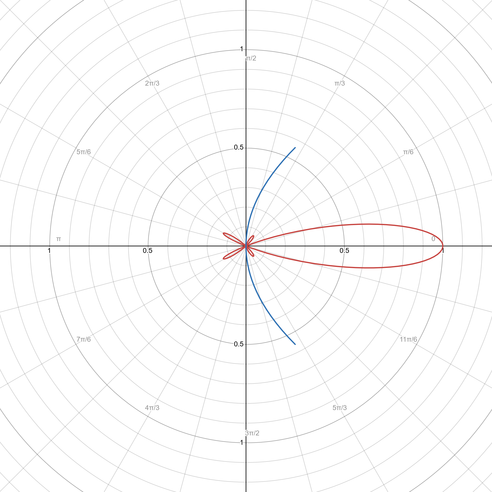
A plot of the electric field (radiation pattern). Note the high directivity of the radiation pattern; the “side lobes” are very small and the light is strongly focused in the “central lobe”. This directivity is roughly proportional to the ratio , meaning that it increases for larger parabolic reflector sizes and for shorter wavelengths.
Note: In the context of optics and RF engineering, the term “radiation pattern” can refer to either the electric field’s magnitude or the radiant intensity3, which is typically proportional to the square of the electric field. Please see
notebooks/parabolic-antenna-radiation-pattern.nbin main Elara Labs repository for interactive plots of both.
It is important to remember that this is an idealized solution that doesn’t account for the non-idealized reflectivity of the mirror, or scattering effects at various points around the transmitter satellite, as previously discussed. It also doesn’t account for the material properties of the mirror, which plays an essential role in how the mirror reflects (and scatters) light. This photonics paper works out the physics for a better theoretical model. However, being an analytical solution, it provides a good baseline result.
Note: A Desmos interactive plot is also available to play around with different parameters of a parabolic reflector and view the radiation pattern.
To incorporate all the effects, analytical techniques will be limited, and we must use numerical simulations to solve the Helmholtz equation on a computer. This is especially difficult when we are working with actual CAD models rather than idealized mathematical models, where it is impossible calculate an exact solution by hand. That is not to say that analytical solutions are not useful; they can provide “good enough” approximations for most purposes, and also serve as a way to sanity-check our numerical solutions.
We can use both finite-element and finite-difference software to do our numerical simulations, although in the finite-difference case we will need to use the cylindrical form of the Helmholtz equation, and we are limited to simpler geometries than the more powerful (but complicated) finite-element method. Currently, we use the FinDiff and FreeFEM++ software packages; the simulation codes can be found in the freefem/ folder in the Elara Labs repository and the simulations/ folder in the laser research repository. An idea that may be worth exploring is using machine-learning solvers to solve PDEs; this may be beneficial since ML-based solvers are meshless methods, which (in theory) are much more computationally-efficient compared to traditional mesh-based methods.
Footnotes
-
Source: https://www.electronics-notes.com/articles/antennas-propagation/parabolic-reflector-antenna/theory-formulas-equations.php ↩
-
While the mirror material (likely mylar, which has a density of around ) is very light, the very large surface area of the mirrors means that the weight builds up. For a 100-meter mirror this is roughly 440 tons, while for a 1km mirror this is roughly 44,000 tons (as much as a container ship). ↩
-
See the Wikipedia article on radiant intensity. ↩