Here, we describe our concept system for space-based solar energy capture and power transmission. The system is designed with several important features in mind:
- It must maximize power efficiency, to ensure that as much collected energy is transmitted as possible
- It must be reliable, to ensure that power beaming is uninterrupted in all weather conditions, even during extreme weather events
- It should be robust and easy to construct and build, to ensure teams all over the world can build the design based on our open-source blueprints
To create such a system, compromises have to be made, and there is no perfect design. Instead, we have tried to come up with a system that, despite its many shortcomings, can best fulfill all of the three requirements.
Note: The term “realistic” in the title should be understood to evoke the idea that the design is physically-sound and theoretically-feasible from an engineering standpoint. It does not imply that the design is simple, nor dismiss the many engineering hurdles necessary to construct it.
The challenge of beam divergence
Of our three criteria, power loss is the most difficult to satisfy. This is because all focused electromagnetic beams always diverge. This divergence occurs at a rate directly proportional to the wavelength and the beam diameter :
Since microwave beams are minimally-attenuated by the atmosphere, they are ideal for satisfying the second criterion. But since microwaves have very long wavelengths compared to visible light or infrared radiation, microwave beams diverge far more quickly. This is a consequence of the diffraction limit, which says that at distance , the minimum beam width (radius) is given by:
We derived this result in Ideal laser beam divergence, and we showed in Computing the theoretical minimum divergence beam that this is a fundamental limit that cannot be overcome. Even in this theoretically-ideal circumstance, a maximum of only of the beam’s intensity can be concentrated in this region (though increasing the ground receiver size to 1.52x the beam width can increase this figure to 99%, due to how a Gaussian beam works). There are some solutions of varying feasibility and effectiveness:
- Brute force: if the beam is simply powerful enough, even a small cross-section of the diverged beam will carry substantial power. Obviously extremely energy-inefficient.
- Lower orbits: using low-Earth orbit (most likely near-polar orbits) the distance the beam has to travel is shortened; therefore, the beam divergence is reduced. This comes with the drawbacks of low-earth orbit (space debris, constant need for station-keeping due to atmospheric drag, crowded orbit, etc.).
- Shorter wavelengths: tune the free-electron masers to a shorter wavelength (millimeter wave) to reduce divergence (which scales linearly with the wavelength). This is acceptable for experimental testing and prototypes, but atmospheric attenuation will make this method extremely inefficient.
- Collimator: use a specialized optics system to expand the beam and collimate it, since wider beams have lower divergence.
- For this to work, we must develop a collimator system that does not obstruct the mirrors and lead to further losses
- One option would be to use a plasma lens: a thin layer of charged particles that is optically-transparent (and hence wouldn’t affect the light-collecting ability of the mirrors) but interacts electromagnetically with the RF beam, similar to the effects of the ionosphere on certain types of radio waves
- Another option would be to situate the collimator far enough away from the power satellites that it is essentially its own spacecraft
- This may benefit from some nonlinear optics; for instance, if it is possible to exploit the optical Kerr effect, then only one lens needs to be used (the lens to expand the beam) and we can rely on a special material to collimate the expanded beam (as long as we can carefully control the refractive index)
- Beam synthesis: use a superposition of beams to reduce the divergence of the overall beam. This is a highly-theoretical approach that we have studied (see Principles of coherent beam synthesis), but its origins in phased-array technology make it grounded in established physics and engineering.
The only realistic method of getting “around” the divergence limit is the last approach (beam synthesis); note that it does not actually violate the divergence limit, for reasons we have discussed in Principles of coherent beam synthesis. However, the development of the technique will take time. In general, we will have to accept that large beam divergences will be unavoidable, at least for our early prototypes, before we have a functioning coherent beam synthesis system. Assuming direct application of the divergence limit formula for 1 GHz waves and for 12 GHz waves in the best case scenario (see Ideal laser beam divergence). This is notwithstanding the fact that any frequencies will likely get attenuated greatly in adverse weather conditions and incur huge power losses, so our best-case spot size (beam radius) for the beam at Earth’s surface is likely to be over a kilometer.
The spot size (beam diameter) of a 2 GHz beam upon reaching the Earth would be around 3.7km wide, which is around the size of a big solar thermal power station’s land area1. This is why we want our stations to built off the coast, where the space-to-Earth beam would be located away from population centers for maximum safety. However, assuming we can cover the entire area of the beam, this amounts to a massive amount of power (though the average power density will be very low and should be as safe as a microwave). For a solar power satellite of our design with 10km radius mirrors, not accounting for inefficiencies, we can generate 427 GW of power, enough to satisfy the power demands of a country.
In reality, however, losses would probably mean an efficiency of only around 10-25%; however, this is still quite substantial, and a constellation of power satellites would have an impressive power generation capability. Larger mirrors (up to 30 km) could provide up to 3.8 TW of power each (in ideal circumstances), making these satellites the most powerful energy generators in the world, and in the vacuum and freefall environment of space, we can go nearly as big as we want. It is certainly not unfeasible, from a purely theoretical standpoint, to achieve something extraordinary: for these solar satellites to power the entire world, and launch us to other planets and even the stars.
Concept design
All of our designs utilize a free-electron microwave laser (maser) as the source of the power beam. A laser has numerous advantages, including a very narrow bandwidth (avoiding conflicts with telecommunications) and high power output. Moreover, unlike most lasers, free-electron masers are designed to be tunable, meaning that their output wavelength can be changed arbitrarily. This allows a lot more flexibility than a conventional laser.
The very first concept design (see the archived sections at the bottom of the page) benefits from using a variety of relatively proven technologies, such as parabolic antennas, waveguides and beam combining. However, it has the disadvantage of being extremely large (power satellites kilometers across) and extremely impractical to build. It is also somewhat wasteful, due to the fact that it requires hundreds of parabolic dishes to be steered for the beam-combining to work. For these reasons, we also propose another design that shares some commonalities but is overall very different.
This newer design relies on an idea very similar to conventional beam combining, but uses an array of spatially-separated power satellites with individual masers rather than parabolic antennas. By physically separating the power satellites in space, their individual maser beams can together create a synthesized beam with a much larger effective aperture size than their individual apertures. The divergence of a synthesized beam, steered at angle made by coherently-combining individual beams separated by a distance is given by2:
The beam width on earth, (i.e. its width by the time it reaches the Earth’s surface) can be approximated as , where is the distance from the source (in our case, we have , the distance from Earth to geostationary orbit). Note how the above expression is completely independent of the size of the individual masers, meaning that we can have a highly collimated beam even with (relatively) small masers, avoiding the need to build one giant laser.
The theoretical basis behind synthesized beams comes from the fact that all electromagnetic waves exhibit interference. Thus, by combining several light (or microwave) sources that are in-phase, constructive interference creates a powerful “peak” of power density in the center of the combined beam. This means that while the system is still bound by the diffraction limit, it can concentrate power more effectively within a smaller radius, which has the same effect as having a larger single aperture. This is why, for instance, existing astronomical radio telescopes such as the Very Large Telescope use a very similar technique by spacing out individual radio antennas over a span of over 20 kilometers to capture as much light (more accurately, radio waves) as possible.
Note: More detail on the theory of synthesized beams can be found in Principles of coherent beam synthesis.
Thus, in this design, we use separate power satellites, each with their own solar mirror and maser, which orbit together at geostationary orbit at a fixed separation of with respect to each other. Each maser is based off the same basic design as our passively-driven free-electron maser design shown below:
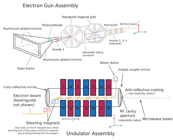
Note: the above diagram contains an error; the magnets should be quadrupole rather than sextupole magnets.
The masers can be tuned simply by raising/lowering the undulator magnets to change the field strength and to move the partially-reflective mirror (iris aperture) mechanically to increase or decrease the size of the resonant cavity (the iris aperture should be able to slide horizontally). This is useful since for prototype testing, it is useful to tune the masers initially to shorter wavelengths to decrease beam divergence.
The output coupler is essentially just an adjustable-size aperture, which helps keep the maser beams as close as possible to the ideal Gaussian beam (conventional waveguides, by contrast, can introduce distortions3). The maser beams are then coherently combined to be able to form an array multiple kilometers across, which creates a highly-collimated beam. Since the power satellites are spatially-separated and there is nothing physically holding them together, we call this arrangement a sparse array. We show the design in the diagram below:
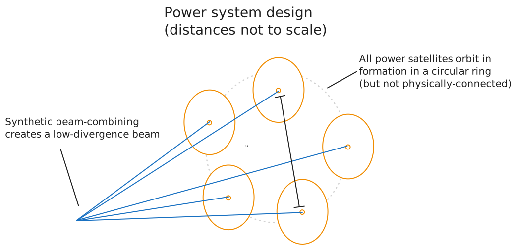
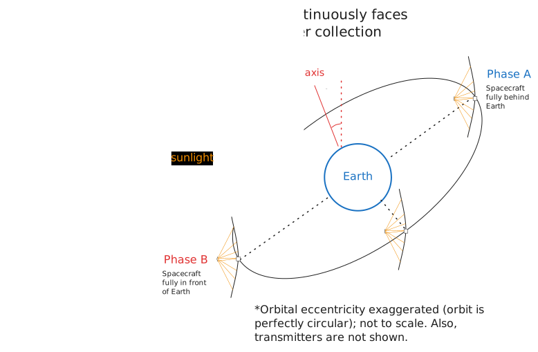
This system relies on precision masers that are all exactly in-phase and aimed at the same direction so that constructive and destructive interference can take place. For the masers to be in phase, they must be monochromatic (producing microwaves at exactly one frequency) and perfectly-synchronized (so there are no phase shifts). This means that the distances between the power satellites must be kept constant to incredible precision throughout each orbit, in a similar fashion as space-based interferometry satellites like the LISA space observatory. For this reason, the power satellites will likely need to adopt a zero-drag satellite design so that the masers can be kept in as controlled an environment as possible. They must do so while keeping their mirrors focused perfectly towards the Sun (as shown in the diagram below), to maintain the maximum solar coverage for power collection.
In addition, since the beams are spatially-separated by kilometers and thus arrive at an angle to the ground, it is also necessary to slightly correct for the phase-shift caused by this discrepancy in path length, even though this discrepancy is extremely small. If we let be the synthesized beam diameter (as with before) and be the distance to geostationary orbit, the path-length difference caused due to the angled approach of the beam is given by:
While it may seem like this path-length difference is very small, it is still around 40% of a wavelength (assuming microwaves), meaning that active phase correction may still be necessary to make sure that the different waves all arrive exactly in-phase with each other. However, using a sparse array power system means that instead of building huge power satellites, we can build much more moderately-sized ones (30-meter mirrors, 1-meter horns, and weighing a few tons) that are well within our current capabilities for satellite construction and can (each) be launched with a single rocket. By simply spacing the individual power satellites far apart from each other, we can create a huge synthesized beam that creates a tightly-focused beam, as opposed to needing ridiculously-sized power satellites armed with a mind-boggling number of antennas.
Note: It is possible to connect all the individual masers to a single large mirror and simply position them at the rims of the mirror, rather than spacing them out in an ring formation (and consequently needing to carefully align their orbits). However, this would only be efficient if the mirror itself was several kilometers across, which would require future technologies to make possible.
Satellite prototype design
Since the system requires no large-scale space engineering and only relies on highly-accurate satellite positioning, the prototype design would mostly be limited (on an engineering level) by the size and weight of the maser and altitude control systems (as well as onboard electronics). While we do not yet know the specifics for how heavy our (fairly unique) free-electron masers will be, we can make some estimates. As our work is currently on building compact and highly-efficient free-electron masers, assuming that we can create a tabletop-sized free-electron maser, it is possible (although not guaranteed) that the maser mass could be brought down to a hundred kilograms or less. Assuming a 5-meter radius and very thin solar mirror made of a roll-able aluminium-coated plastic, it is likely that the mirror mass can be brought down very low - perhaps just a few kilograms. The microwave horn would also be very light. Thus, the majority of the mass would be the altitude control systems, which must be made as light as reasonable.
To ensure a reliable spacecraft, we want to have as few moving parts as possible. The spacecraft would be able to power itself since it acts as an energy converter, and energy recovery systems in the free electron maser can also be used to power the spacecraft. Backup solar panels could provide emergency power in case of solar storms or system failures. For the altitude control system, traditional thrusters and reaction wheels can easily malfunction and have many moving parts. Instead, passive systems can be used, like electrodynamic tethers, which use a conducting rod with DC current to raise (or lower) a spacecraft relative to Earth’s magnetic field, and magnetorquers that work using a similar principle, but for changing orientation rather than altitude. We can also use small secondary mirrors that can be twisted, relying on the radiation pressure gradient from sunlight to help rotate the spacecraft, although this would require mechanical components as well. So, for backup, we would still want some reaction wheels, though technologies like magnetic-bearing reaction wheels could eliminate the friction that can cause mechanical wear and tear on traditional bearings.
For our electronics, we can use cheap consumer-grade devices, much like NASA’s PhoneSat used commercial phones, and of course we would be using open-source technologies like NASA’s F prime open-source satellite control system and our own Project Elara software and libraries. Communications would likely use smaller monopole RF antennas to avoid conflicting with the microwave frequency range used by the maser.
Orbit and positioning
The ideal location for solar energy collection is geostationary orbit. At such an orbit, the power satellites naturally track the ground, reducing (though not eliminating) the need to develop complicated ground-tracking systems. In addition, satellites in geostationary orbit are (for the most part) perpetually facing the Sun, meaning that they can collect solar energy uninterrupted for 24 hours a day.
However, the extreme distance of geostationary orbit means that putting any satellites there will be a major engineering challenge, and it is likely that only the largest power satellites will be located there. Meanwhile, smaller power satellites can be placed in lower orbits but at a high enough inclination so that they are perpetually facing the Sun. Using cylindrical coordinates, if the satellites are a horizontal distance from the Earth, measured along the plane of the ecliptic, then to be in perpetual sunlight their inclination must be at least , where:
Where is the pole-to-pole distance of the Earth (equal to ) while is the Earth’s radius. In practice, this means that if these power satellites are in LEO then they will have nearly-polar orbits, though they can have more moderate inclinations if they are in MEO. A Sun-synchronous orbit is an alternative option worth considering.
Terrestrial receivers
Once our power beams arrive on Earth’s surface, we still need to collect the power and turn it into useful electricity that we can then distribute. For our terrestrial receiver stations, we plan to convert old semi-submersible oil rigs that can be towed by tugboats, and retrofit them with massive collections of parabolic antennas that collect the microwaves from space and convert it back to electricity. This electricity can then be transmitted back to shore with undersea cables. As a bonus, by using old oil rigs as our base, we can make these receivers semi-mobile and able to be towed around the world to supply electricity everywhere. However, owing to the scale of our collectors at 6km in diameter, we will need to combine a large number of old oil rig platforms and will need powerful tugboats to pull the receivers to sea. Additionally, to shelter our delicate parabolic antennas onboard from corrosion and storms, we will need to surround them with radomes. The engineering challenges will be no doubt massive, but this is a concept that could in theory work.
Mitigating divergence and secondary arrays
The primary power satellites, as described above, would be located in geostationary orbit. However, this is a problem, since the power satellites will need very large terrestrial collectors to be able to capture most of the beam as it diverges over the incredibly long distance from geostationary orbit. Even with the beam-combining strategies we outlined above, which does increase the effective aperture and decreases the divergence, the ground-based stations would be still incredibly large. We do partially mitigate this issue by letting our collector stations be offshore and semi-mobile, although this limits access to purely coastal regions.
To mitigate this issue, the plan is to implement an extensive microwave power relay system. By mounting microwave antennas on high, prefabricated towers, we can send power wirelessly from our primary receiver stations at sea to inland regions, while not needing (as much) substantial infrastructure as typical electrical power lines. Since microwaves between barely attenuate in the atmosphere, it is also more robust and not as easily damaged by weather or needing maintenance. A relay of these power transmission towers can bring power far inland, making it much more widely-available. Furthermore, with economies of scale, we can greatly reduce the cost of these towers, reducing the cost of construction as well.
But the problem, of course, is in areas without electrical grids or indeed without much infrastructure at all. While we can subsidize the construction of our power relay system so that these communities do not need to pay the majority of the upfront costs (again, we are not-for-profit after all), building high power transmission towers may take too long, especially when these regions are very difficult for construction crews to reach. These remote and underdeveloped regions need power directly from space. For this, we plan to create a secondary array of power satellites, only instead of being built in geostationary orbit, they are placed in low-Earth orbit only from Earth’s surface in Sun-synchronous orbits that keep them always in full view of the Sun. The much, much shorter transmission distance (compared to geostationary orbit) means that the divergence is much less, so smaller, potentially air-droppable or ship-bound power receivers can be adequate, although the extremely-fast orbital velocities of these satellites in lower orbit relative to the ground means that they need to use sophisticated phased arrays or (as in Concept 2) tightly-synchronized formations to track the ground. In addition, a constellation of satellites would be necessary, as each satellite comes into and out of view of the ground receivers. Needless to say, this is a tremendous technological challenge.
This also allows us to cover for our other use case: bringing power to disaster regions and warzones. A combination of air/helicopter-dropped and ship-bound power receivers would allow much improved access to power infrastructure, which can power medical equipment and other equipment used by humanitarian workers. These can specifically be used to receive power from the power satellites in low Earth orbit, which have much tighter beams and therefore do not need as much infrastructure.
Archived portions
Discontinued concept design: single large power satellite system
Our original first concept design is shown in the diagram below:
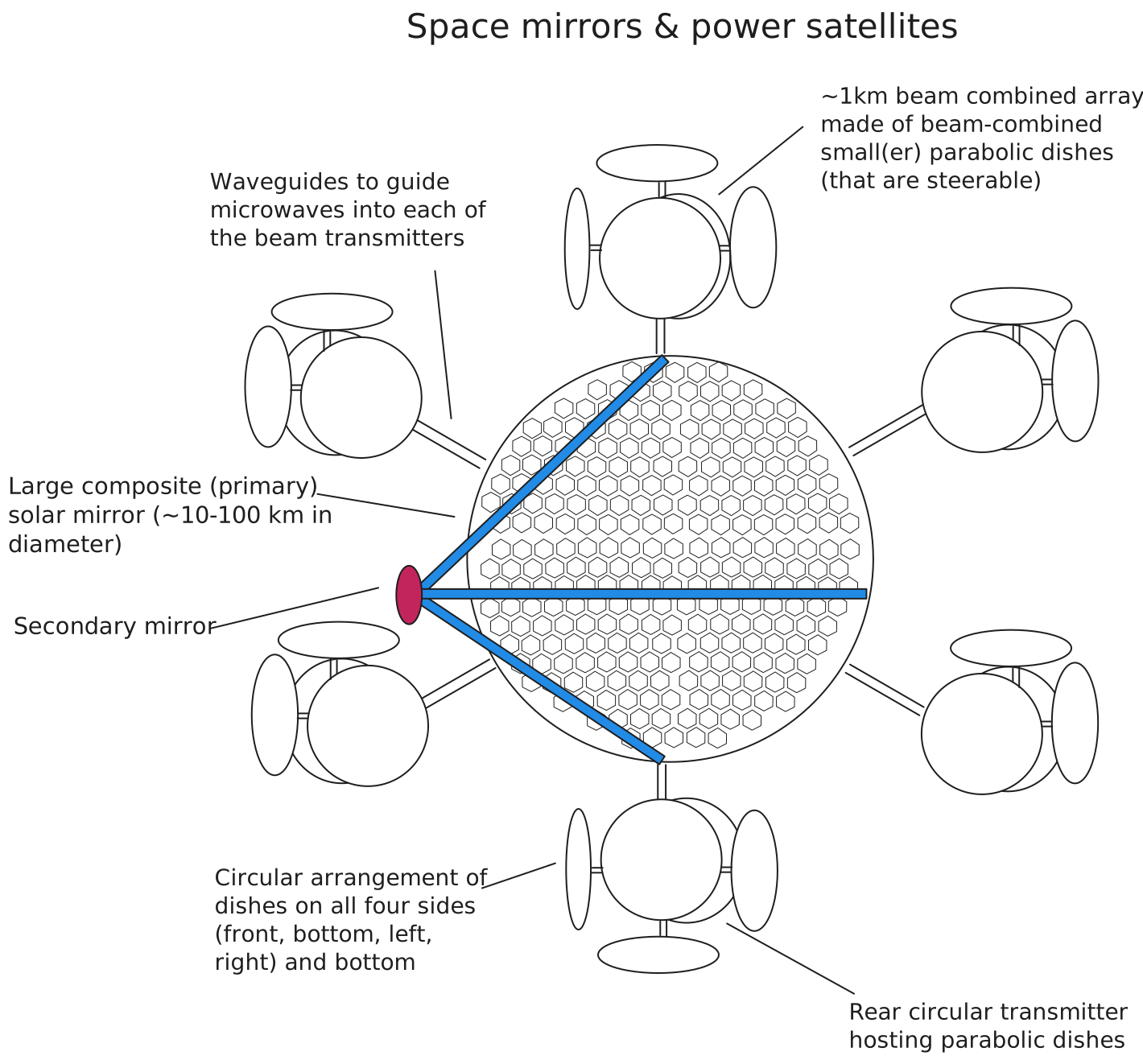
The design, in general, consists of a very large composite solar mirror, made of many smaller segments joined together. The segments are extremely thin and are coated with a very thin layer of a pure, highly-reflective metal. The composite solar mirror is parabolic in shape, and reflects the sunlight onto a secondary mirror (which is also parabolic in shape). The struts used to support the secondary mirror are extremely thin and lightweight to minimize interference. A suitable material could be titanium, although it would be incredibly expensive. The secondary mirror directs the now-concentrated sunlight into a small hole in the primary mirror, where it enters the laser cavity (not shown). The laser is a semi-tunable free-electron maser (or similar) that uses the concentrated heat and UV radiation in the sunlight to cause the thermionic emission and photoemission of electrons from a tungsten (or specialized ceramic) cathode, chosen due to its ability to withstand very high temperatures and its conductive nature. The cathode is negatively-charged, repelling electrons off its surface, which are attracted by a series of anodes and focused with magnetic lenses. The basic design of the electron gun and undulator for the laser would be a variation of the passively-driven free-electron maser design shown below:
The maser produces an intensive microwave beam with a power of several hundred MW (megawatts), and this beam is fed via cylindrical waveguides to circular-shaped transmitters on the sides of the solar mirror. These transmitters are several hundred meters to over a kilometer across, and contain hundreds of small parabolic reflectors (dishes). The maser beam travelling in the waveguide is split among the reflectors, which each have a primary and secondary reflector. This creates a very focused beam. By using reflectors of different sizes in a confocal arrangement and different phases, the smaller parabolic reflectors can effectively combine their microwave beams into a much larger microwave beam, allowing the circular transmitters to have an effective aperture of over 1 km, which, as we know from Ideal laser beam divergence, leads to a highly-collimated beam.
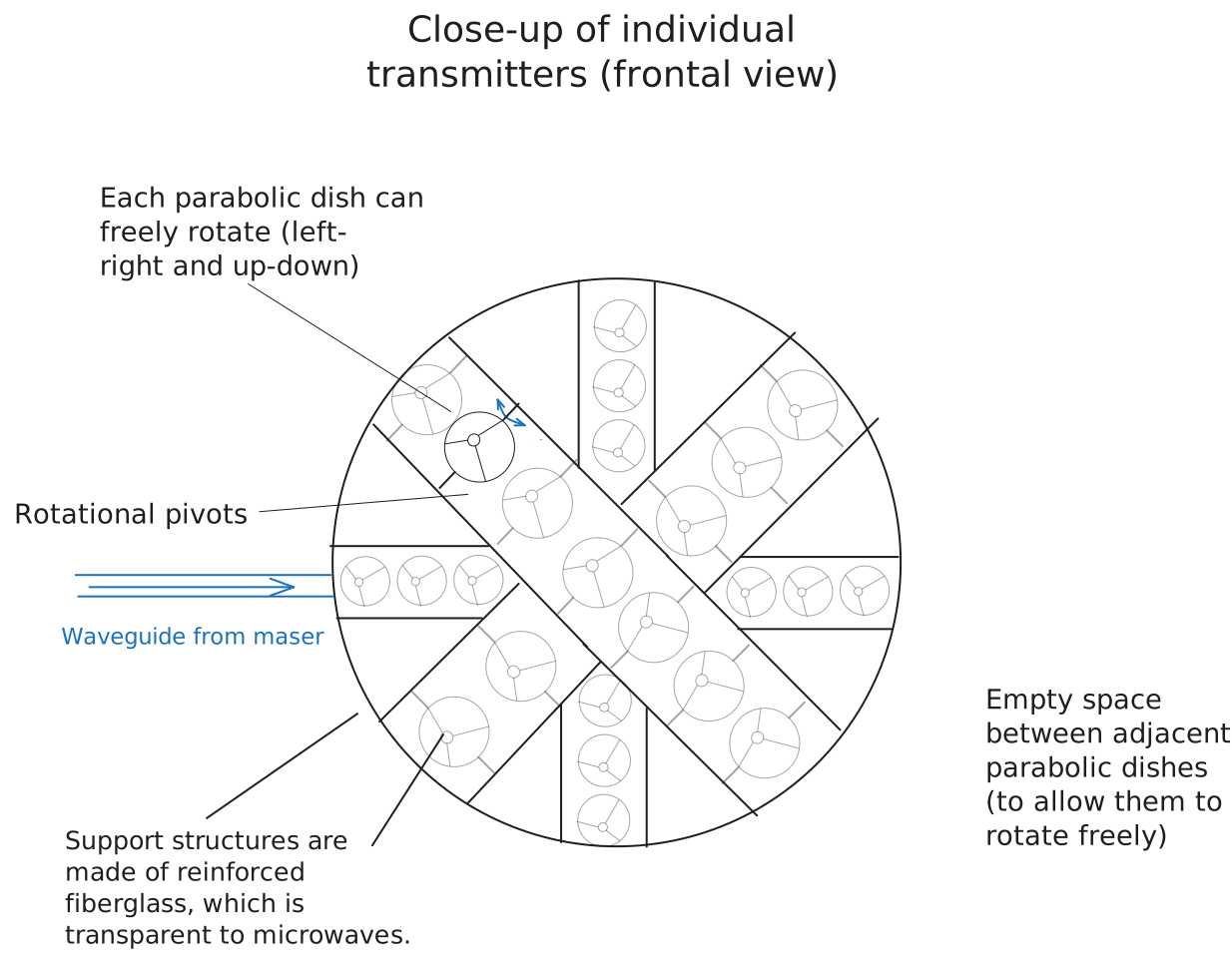
Note: Only a few of the “stripes” of the parabolic reflectors are shown, and their sizes are exaggerated, but in reality, the entire surface of the transmitters would be covered by criss-crossed stripes.
The circular transmitters are attached on all sides of a central hub4, allowing the mirrors to continuously face the Sun while the transmitters always face the Earth. As the spacecraft’s shifts from the night to the day side, the parabolic reflectors rotate to track the ground-based receiving stations. They are mounted on magnetic bearings to minimize friction and avoid moving parts. And since the position of the receiver stations with respect to the spacecraft changes throughout the course of the day, the microwave beam splitter redirects power from the circular transmitters on one side to the next, depending on which is facing the Earth at the moment. This enables the beam to stay locked on the same station(s) throughout the day. Additionally, having transmitters on each side means that the power satellite can send power to multiple stations at once, which, again, is one of our goals for making this a global, international power source.
Footnotes
-
The Ivanpah solar power facility located in the Mojave Desert has a total land area of 1420 hectares. Since its base is roughly circular, its diameter can be calculated from (from , the formula for the area of a circle in terms of its diameter), which evaluates to roughly 4.25 km. ↩
-
See Phased-array analysis for the half-power beamwidth approximation and its sources. ↩
-
An ideal laser/maser has the beam profile of a Gaussian beam and is thus the most tightly-focused beam possible, since the Gaussian beam diverges by the diffraction limit (the theoretical minimum divergence). However, a waveguide’s boundary conditions give rise to modes that disrupt the Gaussian nature of the beam. As the Wikipedia article on electromagnetic modes explains, “hollow metallic waveguides filled with a homogeneous, isotropic material (usually air) support TE and TM modes but not the TEM mode”; since TEM (transverse electromagnetic) waves are non-Gaussian, the beam quality degrades after passing through a waveguide. ↩
-
This is distantly inspired by the AN/FPS-132 Solid State Phased Array Radar System, for instance, at the RAF Fylingales military radar station. In addition, it was also inspired by this concept of a solar-powered space tug, originally from Wikipedia’s article on space-based solar power. ↩
