This guide gives a detailed overview of our design for a prototype free-electron maser that we will be testing (as detailed in Test build of a free-electron maser). If realized successfully, based on our knowledge it will be the world’s first fully open-source free-electron maser design.
Note: This guide assumes familiarity with free-electron masers. See Free-electron maser physics for a more comprehensive guide to free-electron masers.
General design
Our prototype design consists of an electron gun that uses electrostatic acceleration to be able to accelerate electrons to high speeds, as well as an undulator that uses the interaction of the electrons with a magnetic field to generate microwaves. The full design is shown below:

In this design, we assume generic parameters for most values. This is primarily because while we have done some calculations and some numerical simulations, much is unknown. Consequently, most parts of the maser are adjustable. Test build of a free-electron maser has specific suggested values for the parameters for the prototype, based on our theoretical predictions.
Photocathode
We use UV light to stimulate photoemission of electrons, rather than using the more-efficient thermocathode (which uses thermionic emission), as this is an initial design and thermal heating introduces additional complications to the design. A UV light source (e.g. UV-C lamp) is placed and secured by the frontal open frame in the electron gun. The UV light then enters a inlet horn, which is a reflective chamber: all four sides of the chamber are made of thin polished aluminium1, and at the end of the chamber is a small zinc photocathode. Due to the low work function of zinc at 2, a UV-C light source operating at between has more than sufficient energy to eject electrons out of the metal.3
Note: Both the aluminium and zinc (photo)cathode must both be made of pure metal stored in an inert gas or other oxygen-free environment. The zinc cathode in particular must be scoured (polished) to remove the surface layer of zinc oxide that forms due to contact with air.
Additional note: We may end up using magnesium since it has a higher quantum efficiency, though it is harder to obtain and more dangerous to handle. Other possible choices are copper, aluminum, and silver. Please see Test build of a free-electron maser for a table of materials and their quantum efficiencies.
The expected EM field in the inlet horn can be found through solving the Helmholtz equation. A sample distribution is shown below, although note that for visible light, the pattern will be different due to the much higher frequencies (and thus much, much shorter wavelengths) of visible light, meaning that the fields will be highly-oscillatory in both the vertical and horizontal directions:
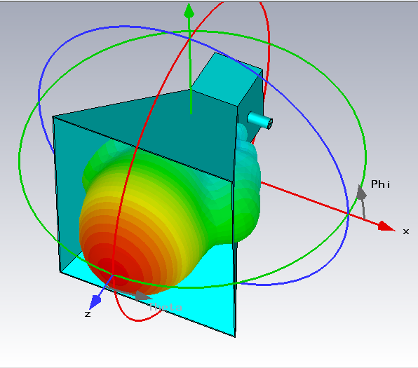
Source: Henrik’s blog
Magnets
In our design, we use three different types of magnets. The first type of magnet is the steering magnet (we can also call it the turning magnet). This type of magnet is a modified version of a horseshoe magnet, and uses two flat magnets of opposite polarities, so that the south pole of one magnet faces the north pole of the other magnet. For instance, the below diagrams shows the N-S configuration shown below (north pole side on top, south pole side on bottom):

Note: The magnets of course themselves both have a north and a south pole. Thus, to be more precise, the top magnet in the illustration would have its north pole on its bottom-facing side, whereas the bottom magnet in the illustration would have its south pole on its top-facing side. This is not shown in the diagram for simplicity.
In the N-S configuration, the magnetic field lines point downwards, so the Lorentz force causes the electron beam to follow a curved path that bends towards the right (remember: electrons are negatively-charged, so they are deflected the opposite direction of positive charges) Meanwhile, in the S-N configuration (where the south-facing side is on top and the north-facing side is on the bottom), the Lorentz force causes the electron beam to bend towards the left. This is used for steering the electron beam from the electron gun into the undulator.
Note: A horseshoe magnet may be used as a low-cost alternative in preliminary experimental testing.
The next type of magnet we’ll use is a sextupole magnet, which is used for beam focusing rather than steering. This is a composite magnet made from six magnets joined together in a hexagonal ring, hence the name “sextupole” (meaning “six poles”), as shown in the diagram below:
Source: ScienceDirect for “Design of the Magnet System for the Super SOR Light Source” (Koseki, 2004)
The magnetic field of a sextupole magnet squeezes an electron beam towards its center, which focuses the beam and gives it a characteristic star-shaped cross section, as shown below:

Source: Wikipedia
Note: More details about the sextupole magnets, including an in-depth mathematical analysis, are presented in Numerical simulations for magnetostatics.
The last type of magnet we’ll use is the conventional dipole magnet (permanent bar magnet), which is extensively used in the undulator. As explained in Free-electron maser physics, the field of a bar magnet can be roughly approximated as a perfect magnetic dipole, which has a well-studied analytical expression for the magnetic field. The field is strongest at the surface of the magnet, where it reaches a value of , where is known as the magnetic remanence and is a property of the material that makes up the magnet(for high-grade neodymium N52 magnets for instance, this value is ). A rough approximation expression for the field is given by:
Where is the distance from the center of the magnet to its surface. This live demonstration on Desmos shows a plot of the field; note that it decays by the inverse cube of the distance, so the field is generally quite weak except in the immediate vicinity of the magnet. Thus, the bar magnets in the undulator are also adjustable in that they can be raised and lowered to adjust the strength of the field, as discussed in the next paragraph.
All of our magnets are adjustable to be able to vary the magnetic fields in the electron gun and undulator. This uses a very simple screw mechanism, where the magnet is slotted inside a plastic sleeve and has a (non-metal) screw attached. Since magnetic fields easily penetrate through the plastic sleeve, it has no effect on the magnetic field, and only acts as a guiderail. Turning the screw allows the magnet to be extended or contracted out of the sleeve, which in turn changes the field strength in front of the magnet. The assembly is shown below:

Output coupler
The output coupler of the maser consists of a circular aperture. The aperture is adjustable in size via a iris diaphragm to control the amount of light (technically, microwaves) allowed to pass out of the maser’s resonant cavity (RF cavity). On the other side of the aperture, an anti-reflective (microwave-absorbent) coating or foam is applied to avoid Fresnel reflection. More information can be found in Test build of a free-electron maser.
Output coupler design (archived)
Note: This is for an older version of the design and no longer applies to our current plans.
The output coupler of the maser is very simple and only consists of a circular aperture that leads to a metal waveguide. The diameter of the aperture is adjustable, so as to allow more or less microwaves through (to adjust the intensity of the beam). Through numerical simulations as well as analytical calculations, we found that purely a simple aperture (circular opening on the side of the maser cavity) would not work as the output coupler: details are in RF cavity simulation with aperture. Thus, an attached waveguide was found to be necessary, and calculations indicated that a basic cylindrical waveguide with no curvature along the optical axis was ideal (see Solving for the fields in a hollow waveguide for details).
Other components
All anodes and cathodes are attached to a variable voltage source controlled by a (shielded) microcomputer (e.g. Arduino). The voltage can be changed to be able to adjust the electron beam energy. The beam dump at the end of a maser is a concrete block to absorb the heat and energy of the electron beam. The electron gun will likely need some form of cooling (water cooling might be sufficient) due to the multiple anodes used to accelerate the electrons and form the electron beam, which will heat up from the current that supplies the applied voltage.
Efficiency considerations and testing
While this is just a prototype, it is still important to keep efficiency in mind to minimize power losses. A large part of prototype testing will be measuring the output power of the maser beam as a function of the input power supplied (both from current necessary to power the UV lamp as well as the voltage used to charge the cathode and anodes). Additionally, it is also important to measure the power output of the maser beam at different angles. Please see Test build of a free-electron maser for more information about testing and measurements.
Future design modifications
While not goals in the first prototype, future iterations of the design could incorporate the following features:
- Partial energy recovery of the electron beam to increase efficiency
- A radome to shield against dust, contaminents, etc.
- Using electrets instead of an external voltage source, so that we essentially don’t need any active power supply for the maser
- Swapping out the photocathode for a thermionic cathode with a tungsten heating element (see Thermocathode design for electron gun), and (eventually) combining it with the solar mirror to create a photon-enhance thermionic cathode (PETE)
- Cooling the maser’s resonant cavity and anode (in the electron gun) to 100K (-173 degrees Celsius) to simulate the very cold temperatures of space; this can be done with liquid nitrogen cooling, although care must be taken to avoid damaging the electronic components of the maser
Footnotes
-
A thin aluminium coating for the reflective chamber was chosen due to the high UV reflectivity, which can reach up to 85% (source: Luminus Devices, 2021). The choice of polishing avoids absorption of UV light and maximizes reflection. Alternatively, electroplating aluminium is also an option, although much more complicated. ↩
-
Referenced from the table of workfunction values for common elements (LibreTexts Chemistry) ↩
-
From , where is the work function, we can calculate that the energy of photons from between is between , which is much greater than the work function of tin. Hence, UV-C light in this range can easily eject electrons out of zinc atoms. ↩