The basics of free-electron masers
At Project Elara, we are interested in making high-gain, all-weather masers for wireless power transmission. This necessitates extremely technologically-advanced laser design. One promising idea is to use a free electron maser.
Unlike regular lasers, free-electron masers do not operate on creating a population inversion in an ensemble of atoms, nor involve any sort of stimulated radiation. However, they produce light with the same characteristics as that of a regular laser, with high directionality, coherence (identical phase), and monochromaticity (light of one wavelength). In this guide, we explore the fundamental physics of free-electron masers.
General design principles
A free-electron maser is composed of two parts: first, an electron source, and second, an undulator (also called a wiggler). Unlike “true” masers, which are fundamentally quantum devices, a free electron maser operates according to classical principles. The basic mode of operation is as follows: the electron source creates an electron beam by some method of accelerating electrons. The electron source does this by applying a high temperature by some means to a negatively-charged cathode, leading to the emission of electrons via thermionic emission. Then, a positively-charged anode attracts the electrons liberated from the material, with the resultant potential difference between the cathode and anode accelerating electrons to incredibly fast speeds (up to relativistic speeds, in fact). An opening in the anode allows the free electrons to exit the anode, becoming an electron beam. Then, the electron beam is passed into the undulator, whereby its interaction with a magnetic field causes the emission of microwave radiation. Much like a traditional laser, an undulator has mirrors on either end: perfectly reflective on one end, and partially-reflective on the other end (called the output coupling mirror or alternatively just output coupler), which reflect the microwaves back and forth, allowing only a small portion of the microwaves through.

Source: ScienceDirect
Design of the electron source
The simplest type of electron source is a vacuum tube (whose design we essentially just described), which relies purely on thermionic emission. However, one or more linear accelerator(s) are often preferred for making higher-energy electron beams, and can be used instead (with us applying necessary modifications to power its electron oscillator(s) with DC current from a thermocouple - more on that later). Another variation, often used for experimental physics, is to use a photoinjector, where a laser pulse is incident on the cathode, replacing the conventional heating element. Combinations of these devices can be used to make even more powerful electron beams. In all cases, one uses magnets to be able to collimate and confine the electron beam; the tighter the beam, the better the performance of the maser.
Design and working mechanism of the undulator
The undulator is where the “magic” of the maser happens. In highly-simplified terms, an undulator is a device that uses a particular arrangement of magnets to cause an electron beam to take a “wiggling” path, thus emitting radiation (like microwaves) as the electrons oscillate back and forth. However, that is too simple for our purposes: we need to take a closer look.
A free electron maser’s undulator can be decomposed into several parts. The first part is the electron beam, which enters the undulator from the electron source, guided by bending magnets. The bending magnets are essentially just two magnets of opposite poles that create an effective magnetic field . By the Lorentz force law, this leads to an acceleration of on the electrons (where is the magnitude electron charge and is positive, and is the electron mass), leading the beam to curve into the undulator.
Inside the undulator, there are two rows of magnets, arranged in alternating order - the first magnet and the second magnet have oppositely-aligned poles, likewise for the third and fourth magnet, and so forth, as shown in the diagram below:

This arrangement of magnets leads to a magnetic field that exerts a force perpendicular to the direction of the electron beam. More strictly speaking, since this magnetic field is produced by the permanent magnets, it is a magnetostatic (time-independent) field - more on this later. As a first approximation, this field is given by1:
Where is the peak magnetic field amplitude, and is the fundamental wavenumber. One may write the peak amplitude in terms of a parameter (the “wiggler strength”), which is given by:
From the Lorentz force equation for the magnetic field, , where , one may show that the path of the electron beam can be found to be1:
Note: this is not the fully relativistic Lorentz force, which is given by , but we will use as a approximation.
Where is the maximum transverse displacement (displacement along the axis) of the electron beam as it travels in a sinusoidal path. Since the electrons in the electron beam are moving back and forth (“wiggling”) as they travel through the magnetic fields of the undulator magnets, they emit synchrotron radiation in the form of electromagnetic waves, which have the associated fields:
Here, is the retarded distance (in this context “retarded” means “delayed”, as electromagnetic waves take time to travel), is the magnitude of the electron charge, and is the transverse acceleration of the electrons (we will derive these formulas later). The mechanism from which incoherent synchrotron radiation emitted by the electrons turns into a laser beam is known as microbunching.
How microbunching works
Synchrotron radiation is emitted whenever electrons move in a magnetic field, and thus experience a transverse acceleration from the Lorentz force. Ordinarily, synchrotron radiation is incoherent; the radiation emitted is not in phase and has a continuous spectrum rather than the monochromatic light desired in a laser beam. This is because synchrotron radiation (unlike antenna radiation or traditional laser radiation) is not harmonic (that is, they are not oscillating sinusoidal waves). Rather, the fields are based off of the Liénard–Wiechert potentials, meaning that the radiated EM waves are proportional to the acceleration of the charges, which comes in a continuous spectrum. This makes them unsuitable for generating coherent light.
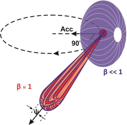
Radiation pattern (power density) of synchrotron radiation in the non-relativistic () and relativistic () regimes. Note that a constant magnetic field is depicted here, whereas an undulator’s magnetic field is spatially-varying. Original source: Bharti and Goyal (2019), Fundamental of Synchrotron Radiations.2
However, in a free-electron laser (or maser), the electron beam interacts with the radiation field (either standing waves of their own radiation trapped in the resonant cavity, or an externally-applied field from a laser or RF source). This radiation field oscillates at a fixed frequency , either by fine-tuning the driving field source or as a natural result of resonance due to the mirrors at each end of the cavity. In the case of the latter, the resonant frequencies are given by:
Where is an integer, is the refractive index of the interior of the cavity (we can generally set ), and is the length of the cavity. A well-designed resonant cavity can be built to select for one specific mode (typically the fundamental mode where ), hence:
This oscillating field exerts a pondermotive force on the electrons, which perturbs the electrons’ trajectories by an amount , where one has3:
Due to the dependence of on , the pondermotive force slows down electrons in regions of stronger field and speeds up electrons in regions of weaker field, creating “bunches” of electrons. And because the radiation field is periodic, this effect is also periodic, leading electrons to “bunch” in groups separated by an optical wavelength . This is what is known as microbunching.
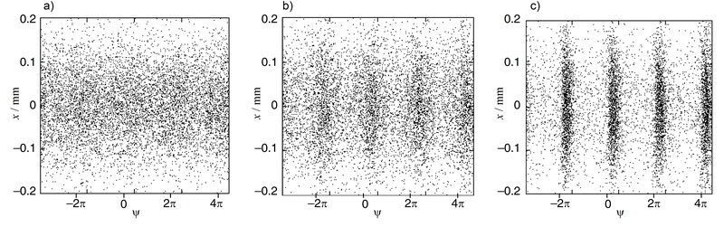
Development of microbunching (images by Rasmus Ischebeck). Microbunching increases from the left to right; note how the right image shows clear “bunches” of electrons separated by a phase of (equivalent to a wavelength in spatial terms).
Each bunch behaves as a single particle, and the bunches radiate in-phase, leading to coherent emission of radiation. For more details on microbunching, consult Schmuser’s Free Electron Lasers in the UV and X-ray regime, section 3.1.2 pg. 27 and these lecture notes on the pondermotive force.
Laser/maser beam characteristics
The radiated wavelength of the maser is the the wavelength of the emitted radiation, which is given by4:
The modes of the electric field in a free electron laser/maser’s resonant cavity depend on the geometry of the cavity. When the cavity’s mirror’s are flat, one has standing modes of plane waves; however, when the cavity’s mirrors are curved (which is used far more commonly) the modes are Laguerre-Gaussian modes due to their cylindrical symmetry (we assume a cylindrical resonant cavity). A real free electron laser beam would be a superposition of these Laguerre-Gaussian modes, but a high-quality laser beam can be modelled as the fundamental Laguerre-Gaussian mode known as a Gaussian beam, where the beam profile becomes a Gaussian. We show a plot of the intensity profile (time-averaged power density) of the electromagnetic field below:

Credit: Wikipedia. Note that in our coordinate conventions, the axis above should be changed to , whereas the axis above should be changed to .
The electromagnetic waves then pass out through the partially-transparent mirror at one end of the free-electron maser, which creates the maser beam. Meanwhile, the electron beam is typically deflected away from the undulator via bending magnets (as shown previously); it is possible to recover some of the energy of the electron beam as the electrons decelerate5, before the slowed-down electrons are deposited onto a large block of dense, heat-resistant material, called a beam dump, bringing them to a final stop.
Note: methods to create a partially-transparent mirror depend on the specific type of free-electron laser/maser. At optical wavelengths (visible light range) it is common to use a mirror that allows some light through. However, at infrared and microwave wavelengths, it is typical to use an aperture (hole) to let out a small amount of the light/microwaves instead (e.g. in Jefferson Lab’s free-electron laser, which operates in the infrared). This also makes sense for very powerful maser beams, which could be well beyond the damage threshold of a solid mirror.
Lastly, we should mention that this is a very elementary discussion of free-electron lasers/masers. Real-world designs often deviate significantly from the idealized model discussed, and also have a variety of features to achieve specific beam characteristics and pulsed operation.
Radiated power of an undulator
The radiated power per electron is given by6:
The intensity of the maser beam is simply this multiplied by the electron flux. The electron flux (the average number of electrons in a beam cross-section per second) can be found from the supplied current (which is a property of the electron gun) and electron charge to be:
Where is the electron beam diameter, and is of , and thus with we have . The intensity of the maser beam is thus given by:
If projected over a circular area of 2 cm in diameter, this would be roughly 4.5 watts of power. Note that the power increases quadratically with number of electrons and thus the current , that is4:
Derivation of the synchrotron radiation formula
The general expressions for the fields of an accelerating charge can be found by solving the (fully-relativistic) Maxwell equations, and are given by7:
Where is the Lorentz factor, is the position of the charge, is the unit vector pointing from to , is the velocity of the charge, and is the retarded time (“retarded” is an archaic term that means “delayed”, since electromagnetic fields take time to propagate due to the finite speed of light). All quantities in the brackets for the electric field are evaluated at the retarded time . In the case of synchrotron radiation, the acceleration of the charges is purely perpendicular to their velocity (and thus also perpendicular to their position ). This means that the charge has no acceleration in its direction of motion and only acceleration perpendicular to its direction of motion.
We are specifically interested in the radiated electromagnetic waves produced by the accelerated charge. Note how the first term in the expression for the electric field falls off as whereas the second term falls off as , meaning that the first portion of the field decays quickly and thus cannot contribute to electromagnetic waves that radiate far from their source8 (“far” being a relative term considering that charged particles like electrons can be tiny). Thus, we can effectively ignore the first term when analyzing the radiation of accelerating charges, leaving us with:
We can clean up the notation by defining and . This allows us to write a more elegant expression, as follows:
In the case of synchrotron radiation, since the charge is accelerating transverse (perpendicular) to its direction of motion, we thus denote the acceleration by . And since , we have . This allows us to write:
Expanding out the cross product, we have , so we have:
Now, since is the (retarded) unit vector, it must have unit magnitude. Assuming that we are examining the transverse radiation of the field (most electromagnetic waves we encounter are transverse waves), then and are nearly perpendicular, so and . By the same reasoning, , and thus we can simplify to9:
Where it is important to note that this is shorthand for:
(Here we must be careful to note that means the transverse acceleration evaluated at the retarded time, that is, is a function of retarded time). An interactive visualization can be found online here.
Optically-pumped maser technology
For our space-based application, we require that our lasers be optically-pumped: that is, entirely (or near-entirely) powered purely by sunlight. This requires some modifications from the standard free-electron maser design:
- The power source for the electron source (electron gun) is sunlight, which heats the cathode, causing both thermionic and photoelectric emission of electrons
- All magnets must be permanent magnets, so that the maser does not need to use energy-hungry electromagnets that would need to be powered by an external source
In the following sections, we will give a basic discussion of the physics of an optically-powered free-electron maser that could work as a space-based power transmission system.
Thermionic contribution
When heated to high temperatures, electrons can escape from the surface of a solid. This is known as thermionic emission and is the principle behind the cathode-ray tube (CRT), a miniature version of the electron guns used in particle accelerators and free-electron lasers.
Thermionic emission is, unsurprisingly, a function of temperature. We may calculate the cathode temperature caused by incident sunlight focused to a spot of area as follows. Let be the standard solar irradiance, be the primary mirror’s surface area, and be the power density of the focused sunlight. Then, by the conservation of energy (total power is conserved and therefore constant) we have:
From which we find that . If we define , where is the radius of the spot that the sunlight is focused to, and , where is the radius of the primary mirror, then we have:
Using the Stefan-Boltzmann law , where is the emissivity, is the power density, and is the Sefan-Boltzmann constant. With a rearrangement, we have:
Letting and , and assuming a tungsten plate (which has emissivity 10), we find that the plate is heated to a temperature of approximately , or about 1500 degrees Celsius - far more than enough to cause the thermionic emission of electrons from a hot cathode. There are also other materials that are especially-suited for cathodes, such as Barium oxide, and can thus produce better-quality electron beams.
Note: The theoretical maximum temperature is around 3,600K - this is due to the fact that this is very close to the melting point of tungsten, which is well-known for having the highest melting point of all known elements. While sunlight can be focused to higher temperatures, and ultra-high temperature ceramics can withstand higher temperatures of up to 4,300K, these materials do not seem(?) to generally be suitable for making cathodes, so 3,600K is a suitable approximation as a theoretical maximum.
The current produced can be calculated from Richardson’s law of thermionic emission, we find that the current density of electrons emitted by a material heated to temperature takes the form11:
Where is the work function of the material (again, for metals this is typically between 2-5 eV12), is the Boltzmann constant, and is the Richardson constant, which is a material-dependent but can be approximated for most materials as . The current is simply the integral over the cross-sectional area of the beam, which becomes:
For large , , but for small , , thus the current grows approximately quadratically with increasing temperature up to a certain point, then decays exponentially. In addition, the current grows linearly with increasing cross-sectional area.
Photoelectric contribution
Since we are using sunlight as the heating source for the hot cathode, we gain some of the benefits of photoinjector, in that we additionally have the photoelectric effect to release additional electrons. We may calculate this contribution as follows.
To start with, the photoelectric effect, as the name suggests, is the phenomenon where electrons are released when light is shined on the cathode. The photoelectric effect contributes to the total electron beam’s current by causing the emission of more electrons from the cathode, where they become free electrons and are accelerated by the potential difference between the anode and the cathode. The greater number of electrons thus increases the current, and thus, by , the power of the electron beam, which directly affects the power of the maser.
The photocurrent density , which is the current produced by the cathode from photoelectric emission of light, depends on the number of photons incident on the cathode as well as a dimensionless parameter , known as the quantum efficiency (more on that later). The precise expression is given by:
Where is the photon flux, which is the number of photons incident on the cathode per unit area per second. We can derive an expression for as follows. First, the total number of incident photons can be found from dividing the energy of the incident light by the energy of a single photon. A single photon has an energy of - this comes from the well-known Planck formula. The total power of the beam can be found from the light intensity and the surface area of the cathode that is exposed to the incident light by (more generally, when we account for the fact that the incident light may be striking the cathode at an angle ). The total energy transmitted by the beam over time is found by simply integrating the power over time, so we have:
Thus. we find that the photon flux is therefore given by:
However, we should note that this assumes a monochromatic (single-frequency) source of light, whereas most light (including sunlight) is a mix of different frequencies over a certain frequency range. For instance, sunlight is composed of a range of frequencies (corresponding to frequencies of 120-1000 THz, or equivalently, wavelengths from 300-2500nm13), as shown by the plot below:

Thus, to find the average photon flux, we must take the average by performing the following integral, where is the minimum frequency and is the frequency range of the light:
And thus our expression for the current density becomes:
The only undetermined factor now is the quantum efficiency , which is likelihood of a single incident photon ejecting an electron. This value is typically a material property that is also dependent on wavelength, so technically speaking, should be written as . Calculating it theoretically is very difficult, so it is usually measured experimentally. We can obtain a ballpark figure by first determining the average wavelength of solar radiation, which we (loosely) term the central wavelength and denote it by . It can be found as follows:
Where is the spectral irradiance of the solar spectrum (power density per wavelength of sunlight), which we just plotted above, and is its inverse function. Evaluating the integral numerically corresponds to a central wavelength of about or a central frequency of about , which we show in the Mathematica notebook in notebooks/solar-spectrum.nb. Experimental measurements of commercial photosensitive devices (used in cameras) at the central wavelength of give values of quantum efficiencies between 45% to 66%14, so . Thus, after plugging in known values for sunlight (which has intensity of about and a frequency range starting at with ), and assuming normal incidence (so ), we have:
In everyday conditions, this does not result in a particularly high photocurrent - for a circular cathode of radius, the total photocurrent is only . However, what is important is that the photocurrent is directly proportional to the light intensity. Thus, by increasing the light intensity (such as by focusing sunlight, say, to an area 10x smaller), then the total photocurrent increases linearly, leading to photocurrents of tens if not hundreds of amps for highly-concentrated sunlight, and contributing significantly to the power of the electron beam.
Note: Of course, our result is an approximation, since the photocurrent does not linearly increase to infinity; a more sophisticated analysis would reveal that the photocurrent eventually reaches a saturation point, but that would involve sophisticated semiconductor physics that we’ll not go into here.
Electrostatic acceleration potential
To be able to accelerate the electrons, a potential difference must be maintained between the anode and cathode of the electron gun. There are several methods to do so, which are discussed in the following section.
Option 1: Thermocouples
One idea is to use a thermocouple as the voltage source to maintain the potential difference between the anode and the cathode. The advantage is that a thermocouple involves no moving parts and has been used to power spacecraft (such as the Voyager space probes) for decades, using the decay heat of radioactive isotopes with a thermocouple to generate electricity. A thermocouple works by the Seebeck effect, where a potential difference (EMF) is induced across a material with a temperature difference acrosss its ends due to the thermoelectric effect. The EMF a thermocouple produces can be approximated by the equation:
where is the Seebeck coefficient of a particular material, and is the temperature gradient (difference between the temperatures of the hot and cold sides of the thermocouple). The advantage of being in space is that the temperature in the vacuum of outer space is just , meaning that the temperature gradient can be in the thousands of kelvin.
If we assume a selenium thermocouple that is attached on one side to the hot tungsten cathode. Using our previous figure of for a hot tungsten cathode, and using the fact that the Seebeck coefficient of selenium is 15, we arrive at a figure of an EMF of around - not substantial, but sufficient to power the electron beam, and definitely enough to accelerate the electrons to substantial velocities (remember: electrons have tiny mass, so even a weak potential can cause a lot of acceleration to an electron!) With more specialized materials (specifically certain types of specialized semiconductors), we may be able to do better - for instance, high-temperature oxides (such as ) can have Seebeck coefficients up to 16, which, combined with a tungsten cathode heated to with concentrated sunlight, may allow reaching an EMF up to . Of course, we wouldn’t have just one thermocouple; we’d want an array of thermocouples, which can then be able to produce an EMF somewhere in the range of to (the low end is about the EMF of the thermocouples from the NASA Mars Perseverance rover17).
Option 2: Electrets
Electrets are materials that have a permanent electrical polarization that gives them a permanent electric dipole moment. This means that electrets produce an electrostatic field, just as permanent magnets produce a magnetostatic field without needing a current source. In theory, if we make the anode and cathode out of electrets, this should mean that we can sustain a potential difference without needing to resort to thermocouples or other power sources. Electrets have been demonstrated18 to maintain a potential difference of up to which should be well more than enough to create a successful electron beam. However, more familiarity with electrets are necessary before we can consider them as a workable option.
More exotic options
In theory, we can choose to use a radioisotope thermoelectric generator (RTG) instead for generating the potential difference without relying on any (onboard) electrical power source, or even more exotic devices such as betavoltaic batteries or stirling radioisotope generators. These are not going to function forever, but can potentially work for 50+ years, or with better technology, perhaps more than a century.
Electron beam power
The end result of both photoelectric and thermionic emission of electrons is the ejection of electrons from the cathode surface. Unlike typical electrons bound to atoms, they are free electrons, hence the term “free-electron laser”. Via a magnetic lens, the free electrons are then collimated into a beam. The power of an electron beam is given by:
Where is the potential difference, is the beam current, and is the current density, which is integrated over the cross-sectional area of the cathode. The beam current is dependent on the type of cathode (photocathode, thermocathode, etc.) but as long as the current density is roughly constant, we have:
where is the cross-sectional area of the cathode. A current density of is achievable with today’s oxide-coated thermocathodes, meaning that beam power in the range of several hundred kilowatts is certainly achievable from solar pumping.
Modelling techniques
In this section, we will discuss a general overview of the techniques to model the undulator. For our purposes, we consider free-electron masers that use only permanent magnets.
A review of magnetic materials
The origins of ferromagnetism are quantum-mechanical in nature. They arise from the nonzero magnetic dipole moments of individual atoms within a magnetic material, which are caused by a combination of the effects of the orbital angular momentum and spin angular momentum of electrons within atoms. You do not need to understand what all of that means - the important point is that even in the absence of a magnetic field, ferromagnetic materials retain their magnetization, so they can be considered to have a permanent magnetization.
Modelling permanent magnets
A permanent magnet generates a static magnetic field, as its magnetic field comes purely from its permanent magnetization, not from moving currents. Thus, the free current is zero, and since the static regime is by definition time-independent, the Ampere-Maxwell law in matter must be modified to:
Note: This is the explanation behind why permanent magnets can only form magnetostatic fields, which we mentioned earlier.
Since the field now has zero curl, it is now a conservative field, which, from a theorem in vector calculus means that it can be written in terms of a potential, called the magnetic scalar potential , by the expression:
The magnetic scalar potential satisfies the partial differential equation19:
The magnetization of a permanent magnet is approximately constant inside the magnet. This is because permanent magnet has an associated remnant magnetic field due to its permanent magnetization, and which is in general a material constant. The strength of this field is called the residual induction or remanence, denoted , which is determined experimentally and usually specified by the magnet’s manufacturer. One then finds the magnetic moment from the remanence via20:
Where is the volume of the magnet, which can be calculated from its geometry, and is the unit vector pointing along the axis of the magnet (which may not be a constant unit vector for curved magnets).
Outside the permanent magnet, the magnetization is zero, and thus the magnetization is in general a piecewise function:
From there, one may impose the Dirichlet boundary condition that the magnetic scalar potential vanishes at infinity (or more realistically, in a numerical simulation, can be taken to vanish at the edge of a large sphere that approximates a large region of space19). Usually, analytical solutions cannot be found, and numerical methods are necessary. We may then use a constitutive relation to find the magnetic field:
Analytical solutions are quite hard to find, and in most cases, cannot be found. To be able to model the magnetic fields generated by real permanent magnets, it is necessary to use far more sophisticated techniques and complex models based on directly solving the magnetostatic equations.
The free-electron maser equations
We can now put everything together to derive a set of equations to describe the free-electron maser (in the time-independent regime). First, we write the magnetic field as the sum of (for the field of the undulator magnets), (for the magnetic field generated by the accelerating electrons), and (the electromagnetic waves in the maser/laser cavity). This does not require any approximations since we know that the magnets are permanent magnets, and magnetic fields (just like electric fields) are linear and can be superimposed. Thus we have:
Where may be solved for via:
Meanwhile, the electric field is a combination of two parts as well. The first part, which we term as , is the electromagnetic radiation radiated by the charges (electrons) from a combination of their transverse (synchrotron) and longitudinal (pondermotive) acceleration. The good news is that there is a well-known analytical solution for the radiation generated by moving charges - Jefimenko’s equation for a point charge - which is also relativistically-correct. It is given by:
Where we must be careful to use the retarded time for the position of the electrons, that is, , and we have (as before):
And where the electron trajectory comes from solving the relativistically-correct version of the Lorentz force law:
By contrast, the second part of the electric field, which we term as , is the electromagnetic field of standing waves in the optical cavity (since the cavity is a resonator and thus leads to standing waves). Unfortunately, the standing waves inside resonant cavities only admit analytical solutions for relatively simple geometries. Otherwise, it is required to solve the Helmholtz equation, which is essentially an eigenvalue equation for the vector Laplacian of the electric and magnetic fields:
The total electric field is thus given by:
Collecting all our previous results, we obtain the following system of differential equations for the free-electron maser, where we solve for the trajectory of the electron beam, as well as the static () and radiative () fields, giving us a system of differential equations (both ODEs and PDEs) to solve simultaneously:
Where again and come from the equations for the field of a moving point charge. Unlike our previous theoretical models, this is an exact model that doesn’t use many approximations. We can find analytical solutions when we consider relatively simple cases, but not in the general case, in which numerical simulations are needed. Ideally a multiphysics simulation would solve all of these differential equations simultaneously, but in practice it is far easier to analyze solve each part of the system separately, and that is the approach taken in the majority of our research.
Moreover, the magnetic fields is not of significant importance21, and the interior magnetostatic field of the undulator magnets is generally unimportant22; hence, by considering only the exterior field (where ) one simply has . In addition, the electric field of the charges can be simply included as an effective potential that perturbs the electrons’ trajectories. Thus, we can drop it from the electric field, meaning that we end up with . Hence the system reduces to just four equations:
Free electron masers vs. gyrotrons
Finally, we should discuss a related technology: gyrotrons. Gyrotrons are incredibly similar to free-electron masers, in that they use an electron beam of electrons emitting synchrotron radiation to produce microwaves, and an optical cavity to cause those microwaves to form a coherent beam.23 However, instead of using an undulator, they use a superconducting magnet that causes their electron beam to take a helical path (rather than the “wiggling” path of an undulator). They may be a worthwhile technology to investigate separately. For more information on a comparison between free-electron masers and gyrotrons, please see Thumm (2002) and Thumm (2020) (the latter is recommended as it is more recent, but consult both for a comprehensive overview).
Further reading
Please see the below pages for more information:
- Combined system efficiency calculations and Free-electron maser efficiency calculations for detailed discussions of determining the efficiency of a free-electron laser/maser
- Guide to modelling permanent magnets and Numerical simulations for magnetostatics for calculating the magnetic fields of permanent magnets
- Guide to modelling electron beams and Numerical modelling of electron beams for modelling electron (and in general charged particle) beams
- Prototype solar mirror design and Test build of a free-electron maser for Project Elara’s specific free-electron maser design
Footnotes
-
From Jackson, Classical Electrodynamics, 3rd ed. Chapter 14.5 (pg. 677). Note that Jackson gives where , but here we use the notations instead (equivalent to and other than in notation) since it is more frequently used in the literature e.g. in Varro, Free Electron Lasers (2012) ↩ ↩2
-
The radiation emitted by accelerating charges is, at least at low velocities, approximately torus-shaped. However, synchrotron radiation of highly-relativistic particle beams has a more oblong radiation pattern, which is due to relativistic effects. ↩
-
See these lecture notes by Michael Fowler at the University of Virginia, which are based off Landau & Lifshitz’s Mechanics. The given equation is where is the perturbation and (where are constants); however, here is used for greater clarity, and we discard the sine term since it is not important for the proportionality relationship. ↩
-
From the CERN accelerator school’s slides for an Introduction to Free Electron Lasers (2012). Note that the explicit formula given for coherent emission of radiation is but since the total power is proportional to the square of the total electric field strength, it increases quadratically with the number of particles (where is the number of electrons) and thus likewise with the current. ↩ ↩2
-
See Schmusser, Free-Electron Lasers in the Ultraviolet and X-Ray Regime (2nd. ed.), Ch. 2, eq. 2.21 (pg. 18) ↩
-
See the associated Wikipedia article ↩
-
From the Physics 222 course web notes from the University of Tennessee, quote: “The radiation field Erad produced by an accelerating point charge decreases as , while the static Coulomb field decreases as . The static field decreases with distance much faster than the radiation field, and therefore the radiation field will dominate at large distance for accelerating charge distributions. ↩
-
Also from the Physics 222 course web notes from the University of Tennessee. They give the equation as , where is the “…distance at some earlier time, called the retarded time, when the radiation field was produced”, which we write as . ↩
-
From a table of emissivity values ↩
-
See Wang and Yu (2023), Principles of photocatalysis, “Solar spectrum”, https://www.sciencedirect.com/science/article/abs/pii/B9780443187865000020 ↩
-
From Scientific Imaging. Data taken from the interactive comparative QE curve plot at . ↩
-
See this answer ↩
-
See Ye et. al. (2017), https://pubs.rsc.org/en/content/articlehtml/2017/tc/c6tc04594d ↩
-
According to the official NASA documentation on the RTG of the Perseverance rover ↩
-
According to section 2.1 of this paper ↩
-
From the mathematica tutorial ↩ ↩2
-
From Physics Stack Exchange ↩
-
This is because radiative magnetic fields (whether caused by radiating charges or standing waves in a cavity) are generally weaker by a multiplicative factor of . ↩
-
This is because only the external field influences electron trajectories; nothing is moving into the interior of the magnet itself, hence the interior field does not play much of a role in the physics of the system. ↩
-
More details in the Gyrotron wikipedia article ↩